• Due to ongoing issues caused by Search, it has been temporarily disabled
  • Please excuse the mess, we're moving the furniture and restructuring the forum categories

[Merged] Thread to Discuss The Excellent Analysis of Jones latest paper

The Big Dog

Guest
Joined
Jul 26, 2007
Messages
29,742
JREF member Sunstealer has done a very credible job in discussing the article recently paid for by Professor Jones. Notably, this technical analysis is based on the data published in the article itself. It is located here:

http://www.internationalskeptics.com/forums/showpost.php?p=4607894&postcount=1694

This post is taken from a closed thread, and I am following up certain moderators' suggestions that a separate thread be opened to discuss this analysis. I have also asked that it go directly to moderation.

Thanks and enjoy in moderation!
 
Last edited:
JREF member Sunstealer has done a very credible job in discussing the article recently paid for by Professor Jones.

I find it hard to believe that the only possible explanation for Professor Jones' data is SunStealer's interpretation. Below, I reproduce my posts suggesting other ways to get platelet morphology aluminotherics. I made one essential correction. The text now reads "Besides packing more Al per unit volume, a platelet morphology, by maximizing the ratio of Al to Al oxide, ...." , instead of "Besides packing more Al per unit volume, a platelet morphology, by minimizing the ratio of Al to Al oxide, ...."

==========================================

Playing with Platelets

There may be other options. E.g., you can buy silicon in nano-scale platelet form.


You can deposit Al onto silicon via sputtering.

( and perhaps other methods of physical vapor deposition? not sure if this means elemental Al )


As for the motivation to do so, I have absolutely no idea about cost (and absolutely no intention to research it), but aside from that, referring to "MODELING THE MELT DISPERSION MECHANISM FOR NANOPARTICLE COMBUSTION"

we see that:

nanometer scale spherical particles in nanothermite are 20-120 nm

oxide shell thickness is 1-8 nm

consider middling values of 50 nm and 4 nm, about 26% of your particle is taken up in the oxide shell. You are also wasting the space in between spheres.

Perhaps platelets made on nano-silicon platelet substrates help you pack more elemental Al, per unit volume. Especially if Al-oxide shells are "sticky" as they form Al nanothermite in the normal, spherical form, thus leaving huge pockets of empty space to fill. (BTW, IIRC, the Ph.D. thesis I linked to gets into compressing nanopowders. If not that one, then definitely the master's thesis mentioned above.)

If it does this, and saves you money, that would be a double motivation for doing so.

Once again, I remind everybody that I am not a domain expert. Thus, my sputtering speculations may sputter!


Playing with Platelets, part 2

Another speculation as to platelets vs. spherical:

The MODELING thesis says:

Quote:
A combination of increased oxide shell formation temperature and increased oxide shell strength could be used to maximize the flame velocity in particles with increased relative particle size.


Besides packing more Al per unit volume, a platelet morphology, by maximizing the ratio of Al to Al oxide, might result in not just more energy, but relatively less power (i.e., a slower reaction). For one thing, I expect the oxide layer to break near the platelet edges (this is an uneducated guess, I hasten to add), and to do so under less pressure than would be required to break an oxide layer of equal thickness in the spherical case. * This would tend to negate the dispersion melt mechanism as a contributor to flame propagation. Hence, your nanothermite will have it's power profile shifted back towards that of the micron-thermite type, while simultaneously generating more total energy.


If you look at Fig. 1 of MODELING, you can see that Aluminothermics already have dramatically superior energy density (per unit mass) than high explosives, but the energy density, per unit volume, of Al/Fe2O3 is only about 40% greater than high explosives. You can't change the inherent mass of reactants, but you can fiddle with the density. If you simultaneously increase the energy per unit volume, while slowing down the reaction, you can end up with a hotter, but quieter "explosion".


* from MODELING:
Quote:
The pressure inside the Al particle causes tensile hoop stress (σh) in the oxide shell. Due to the small thickness of the oxide shell (1 – 8 nm), it is almost defect free and therefore its ultimate strength (σu) approaches the theoretical maximum strength of alumina (σth) estimated at 11.33 GPa [11].
 
I am very appreciative of the moderated status of this new thread.

As it is new, and so as not to lose my points/areas of concern, I will restate them here.

1. Jones' Analysis was biased, and focused on finding a particular outcome from the get go. As a result, the analysis and subsequent paper ignore, or at best GLAZE OVER the issue of other possible sources of their Red/Grey Chips.

2. Jones' did not address, outside of a dismissive "it is contamination" the presence of Chromium and Zinc in at least one sample, and with this in mind, the possibility that the Sodium spikes in the Spectra, may have also been Zinc. There was no washing of the samples in order to eliminate contamination as a possiblity (or to rule it in).

3. All of the other LEGITIMATE analysis of dust from the WTC GZ had a considerable quantity of Paint in the dust samples. Yet there is no mention of paint particles within the samples that Jones had, and if they were found, how they were separated from the red/grey chips. I find the magnet method poor, because as we all know, paint from the WTC could have been found in the form of bilayered particles, due to peel off or rust/corrosion, and as a result, a magnet would work on them also.

4. I have a problem with the Journal that Jones selected to submit/publish his article with. There is mention of a personal connection between one of the lead scientists producing the paper, and the editorial board. There is a wealth of information indicating that the journal is a "Vanity" "Pay to publish" journal that solicited for members of the editorial boards for its various journals via viral email schemes to unqualified, unrelated (in field of knowledge) academics.

TAM:)
 
I'll start by thanking 16.5.

I planned to do something similar, but it seems the original thread has ended quicker than anticipated.

I also think it's essential that a link to Jones' (God someone put me out of my misery and tell me that damn apostrophe is in the right place or that I need to add an S or ES or something!) paper is in order otherwise we won't know what we are talking about, eh 16.5? ;) :p

http://www.bentham-open.org/pages/content.php?TOCPJ/2009/00000002/00000001/7TOCPJ.SGM

I suggest people download it and open it whenever they wish to comment because it's going to get referenced alot. When people quote from the paper it helps immensely if the page number, the chip sample (*see below) and/or the diagram or graph (Fig #) is also stated so that it can be referenced quickly.

In time I will get a better prepared and fully correlated response using material from the other thread (better google cache that then!) and other sources. You'll all be aware that anything that isn't on the web doesn't exist, so I need to ensure all sources have links etc. ;)

I'd also like to say that there were a couple of posts I would have liked to have replied to in the closed thread, because they were relevant ones and deserve a scientific and civil response namely Bill's and metamars

I'm sure I'll have time to answer them, in the mean time here is a table (or maybe pic if I can get it sorted at this late hour) that breaks down the samples in Jones' paper and shows which experiments were carried out on each sample (that helps everyone understand what was done to each) therefore enhancing understanding. It might not be 100% correct at this moment, because I've still still look at post DSC; photo/SEM/EDS analysis in depth (and word 2007 is a PITA- grrrr [yes I know open office but I don't have it on this machine). Feel free to comment/correct/ask questions though.

* Do people agree that the following is correct so far? It's not crystal clear from the paper, but I'm working my way through it - boy does that take time. Any comments would be helpful - this is a WIP.

picture.php
 
I have not read the original post but I independently reviewed Jones' paper and concluded the following:

Jones investigates only the red and gray chips and not the entire sample. He has a limited sample size. The chips have a laminar nature which suggests a coating or adhesive but he rules out paint by comparing the effect of MEK on some unknown paint and comparing it to the effect on the red chips. This is either incompetence or scientific misconduct and fraud.
He sees that there is an organic fraction but does not analyze it. He uses DSC to measure exotherms but does it in a stream of air so he cannot tell the difference between a reaction and plain combustion of components but claims thermitic reaction. His EDAX shows silicon, aluminum, and oxygen in the same areas of the particle but he ignores this congruency; aluminosilicates are clays and are often fillers in paints and coatings. He does not extract a larger sample of the red and gray chips with a more agressive solvent, such as hot DMF or DMF-DMSO which would allow analysis of individual components.

His conclusion that this is a thermitic material is not justified based on the data.

I have not reviewed the paper in depth, but that may be a waste of time as it is fatally flawed, in my opinion. I estimate that the samples are a red oxide primer on corroded steel.
 
Jones' samples do not appear to me to all have the exact same make-up. There is zinc chromate, an obvious indicator that we may be looking at rust-inhibiting paint, in some of them, but not in others. There are varied concentrations from one chip to another of those elements which are found in all the chips.

Excuse me, but, if you are going to the trouble of producing nano-banano demolition films, are you not gooing to take steps to ensure that each anmd every piece of it is the same thickness and has the same concentration of each and every reagent? I fail to see how the sooper-dooper ther*te would function in anything like a predictable manner if there were expanses of the film over which not all the neccessary components were found.

Paint is, however, quite another matter.

If the vehicle is evenly distributed throughout, it is going to work as paint The vehicle is an utterly homogeneous liquid substance. It suspends the fillers and pigments in order to stick them to the surface to be painted.

If it is not stirred properly, the fillers and pigmments will be present in different concentrations throughout a sample of still-liquid paint, perhaps in a thick paste at the bottom of the can, or layered with different concentrations of filler and pigment up and down the column. The vehicle is, however, not in any way altered.

So, we stir the paint and begin painting a large job of structural steel, and then pause before another batch, but out belly buttons are punching us in the back and urging us to complete this run before 1200, so we do not bother to stir the paint again.

By this time, there is a thin layer of nearly clear vehicle sitting on top of the reservoir, a heavy concentraion of kaolin at the bottom, and layers with a lot of zinc chromate, layers with a lot of iron oxide, layers with a lot of Titanium white and so on throughout the reservoir. The resulting applications will not be of a uniform hue or density of color and it may be a little sluggish comiong out of the nozzle as you start to draw in the bottom stratum of solids, but the vehicle is still going to stick to the steel and harden into pretty nearly the same sort of material throughout the process. It works perfectly, within this context.

It's just unaesthetic.

Inconsistant paint works, sort of. Inconsistant therm*te does not, usually.
 
Playing with Platelets

You can deposit Al onto silicon via sputtering.

( and perhaps other methods of physical vapor deposition? not sure if this means elemental Al )

Dr. G. informs me that sputtering is very expensive. (Page 3, here.) It would cost hundreds of dollars to coat just 1 teaspoon. I don't know about the practicality of depositing the Al via vaporizing it thermally in a vacuum, then gradually re-introducing air, but I have calculated that the energy input to vaporize 10 short tons of aluminum is only on the order of $4,000. (I assumed that oxygen to make a forced flame would roughly equal double the cost of the oil, which is a sheer guess.)
 
Sunstealer:

A question;

The length of time the samples were stored (6 years) and the method (whether they were stored in the dark or light, plastic bag or not, etc....) of storage, can these have an effect on the essential make up of the chips? Specifically, can chemical reactions occur over time, or with improper storage, that might make some of the elements that may have been in the chips disappear (ie become part of a compound outside the chip) or make certain element appear that would not have been there in the beginning, but began present overtime?

Thanks

TAM:)
 
I find it hard to believe that the only possible explanation for Professor Jones' data is SunStealer's interpretation. [snip]

Just a quick comment, early in the thread. Sunstealer's interpretation may or may not be the best interpretation--to my eye, it appears to be a better one than Jones' interpretation, but I am no expert--but it does not have to be. Sunstealer's interpretation is sufficient to point out important flaws in Jones' analysis, and this is all it needs to do.

If a chemist finds a brand new reaction, and someone points out that her test tubes were dirty, the proper response is not to argue that dirty test tubes don't matter, but to redo the experiment with clean test tubes. Sunstealer has pointed out enough problems that the ball is back in Jones' court. The burden of proof is where it should be--on Jones.
 
Very, very interesting admission by Jones et al upon questioning via email by Dr. Greening...

So when I bounced my calculations and conclusions off Jones et al, all he could come up with was the suggestion that there were probably other explosives used in the WTC and the nanothermite chips were maybe just fuses!

Thus, after all the fuss about high-tech nano-thermites, we are back to good-old "bombs in the buildings" as the answer to how the buildings were destroyed.

http://the911forum.freeforums.org/active-thermitic-material-in-wtc-dust-t150-30.html

Yes you read it correctly, Jones seems to be back tracking, CONSIDERABLY, to declare that the last several years of thermite talk, has been for Explosive "FUSES"!!!!

I am speechless.

TAM:)
 
He uses DSC to measure exotherms but does it in a stream of air so he cannot tell the difference between a reaction and plain combustion of components but claims thermitic reaction. His EDAX shows silicon, aluminum, and oxygen in the same areas of the particle but he ignores this congruency; aluminosilicates are clays and are often fillers in paints and coatings.

Exactly. Thermite works in a vacuum. You cannot ignite paint chips if yopu hit it with the heat of a ton of thermite in a vacuum.

Way to hit the floor with both guns firing on your first post.
 
Even if we were to hypothetically accept this as valid.

I don't see how we can go from, "hey we found a few weird flakes of something that could be thermite" too, "it can only be evidence that completely confirms, 9/11 was a done by our own gov't in a big conspiracy by some evil secret NWO group to control the world".

The leap into imagination would still be just as mind boggling.
 
Very, very interesting admission by Jones et al upon questioning via email by Dr. Greening...


http://the911forum.freeforums.org/active-thermitic-material-in-wtc-dust-t150-30.html

Yes you read it correctly, Jones seems to be back tracking, CONSIDERABLY, to declare that the last several years of thermite talk, has been for Explosive "FUSES"!!!!

I am speechless.

TAM:)

Much ado about nothing. The chips were announced in 2007. I believe that that's the first year they were studied. Jones' first paper presenting the thermite hypothesis was earlier. Also, he's previously said that he believed there were a couple of forms of thermite.

His recent paper deals with whether or not nano-thermite is present, not how it was used. Frankly, I don't think Professor Jones cares how it was used, exactly.

What is important is whether or not it's thermite, paint chips, or some other mundane material. Speaking for myself, I'll probably devote some time, in the next few weeks, to printing out a few copies and seeing if the physicists and materials scientists in town have an opinion. I'll also print out the photo of kaolinite, and show them that. However, I have my doubts that it's kaolinite. See my next post.
 
DSC for kaolinite doesn't match Jones' samples

First off, I must point out again that I have very limitied knowledge and ability in these matters. I am presenting my observations as a very slightly educated guess, and not a strong assertion of fact.

If you look at p. 1260 of the Second Edition of the Encyclopedia of Surface and Colloid Science you see two spikes, in the DSC graph of raw kaolinite, figure 4 (a). The first one, which is completely missing in the Jones' DSC plots, is at what looks like 50 C. The second spike is at about 525 C.

In figure 4(b), they show a DSC for Kaolinite-DMSO. There are still spikes at 50 C and 525 C. There is also a new spike at about 180 C. The key observation which I make is that adding crap to the kaolinite doesn't move or remove raw kaolinite spikes. Is this always true? I frankly don't know. But, if it is true, then the Jones' samples are not kaolinite.

I hope SunStealer will comment on this.
 
DSC peak dependence on Temperature for AlMoO3 aluminothermic

Figure 5.8 ( p 83 of the paper; the 104th page counting pages before page 1) of COMBUSTION CHARACTERISTICS OF A1 NANOPARTICLES AND NANOCOMPOSITE A1+MoO3 THERMITES shows the dramatic difference that Al particle size has on DSC peaks, for the case of Al/MoO3 aluminothermic. They plot, on the same graph, the DSC's for Al particle sizes of 40nm, 50nm, 80nm, 120nm, 1-3μm, 3-4.5 μm, 4.5-7μm, 10-14μm and 20μm. The larger the particle size, the higher temperature you need to hit the biggest peak.

(Actually, it looks like 1-3μm and 3-4.5 μm do not follow this general trend, but those peaks are very close.)

The DSC peak for the fattest Al particle, the 20μm, occurs at about 1010 C. The peak for the smallest Al particle, the 40 nm one, occurs at 500 C. Jones' DSC peak. for what he suggests is Al/Fe2O3 thermite, is in the 415 - 435 C range.

Notice, also, that this dramatic drop of DSC peak temperature with decreasing particle size puts to bed the egregiously wrong notion that there's nothing special about nano-scale properties, which some people were proclaiming in the first JREF thread on this subject.
 
A question about the post linked to in the original post: where does the kaolinite with gypsum spectrum come from?
 
Sunstealer:

A question;

The length of time the samples were stored (6 years) and the method (whether they were stored in the dark or light, plastic bag or not, etc....) of storage, can these have an effect on the essential make up of the chips? Specifically, can chemical reactions occur over time, or with improper storage, that might make some of the elements that may have been in the chips disappear (ie become part of a compound outside the chip) or make certain element appear that would not have been there in the beginning, but began present overtime?

Thanks

TAM:)
EDS/EDX/XEDS basically will tell you what elements are present - and that's about it really. If a chemical reaction occurs within the sample itself then the EDS will show exactly the same spectrum as before - XRD will show the difference. The case where that will be different will be if the sample has oxidised (therefore should get a larger O peak) or it's come onto contact with another material which either contaminates the sample or reacts with it.

So as long as they were stored in a sealed plastic bag there won't be any problem.

However, it is true that reactions occur over long periods of time, eg: plastic left in sunlight, we've all seen computer parts turn that nasty yellow colour. Light could also effect the samples, but I doubt this - no one is going to store these outside of a draw/case etc.

Al/Fe2O3 powder particles are not going to be affected by everyday light. The Carbon matrix, which is binder in the samples might, but we have no idea what that specifically is so it's impossible to comment.

Everyone knows that I think the sample's red layers are paint (and not paint from the same source or composition I might add) and these will certainly take a long time (because they are engineered to last as long as possible) to change their characteristics and by that I mean drying out, flaking and cracking or colour change due to light.

I don't think that the length of time stored is any factor - the likelihood is that these chips have been exposed to the elements for just as long as, if not longer than the time stored, as part of the paint that was originally applied to who knows what. No one can say that these samples came specifically from the WTC or any other source - more on that later.

Just had a strange thought about carbon dating the "red layer" but I suspect that technique is not accurate enough to determine differences in such small time scales.
 
I have updated the "specimen test table" for Jones' paper - see below. This now gives us a clear indication of which tests and consequent analysis was performed on each sample of the paper.

It is now easy to cross compare samples and the tests carried out as well as see the source of each sample. Note - what Jones calls samples I call specimens and I use the term sample for the dust samples, but I shall revert to calling specimens as samples when referring to the paper to avoid confusion.

I hope it's readable and not too small - "ctrl and +" for firefox users to enlarge.

picture.php
 
'Notice, also, that this dramatic drop of DSC peak temperature with decreasing particle size puts to bed the egregiously wrong notion that there's nothing special about nano-scale properties, which some people were proclaiming in the first JREF thread on this subject.'

This is of course a misrepresentation of the discussion on Nano-scale properties from the previous thread - I see Metamars also posted the exact wording on the 9/11 forum.

I still have not seen any scientific proof which shows that the combustion temp of real nanothermite is 430c or thereabouts. I also find it very, very strange and somewhat suspicious that Jones et al did not test:
1) actual WTC paint chips (identified properly as such)
2) real nanothermite with similar chemical composition to the famous red/grey chips for comparison

I can't help but feel this latest paper is not actually a very thorough effort to discover the truth except in a very half-hearted way, but is heavily geared towards producing a predetermined result with much ambiguity.

I mean, very simply put, it would have been necessary to demonstrate the chips were able to combust WITHOUT an external oxygen source. This was not attempted!! As definitive proof (to anyone who is slightly skeptical) it automatically fails.

Unfortunately what it DOES do very well is provide yet another source of rampant speculation for devoted conspiracy theorists. It seems this is the real audience the Jones et al are pandering to, and developing their careers and cottage industry from.

I guess you could characterize it as a sophisticated marketing effort at this point. I see very little chance that this paper will be much more than a curiosity for the established scientific community. Much more work will need to be done to 'prove' that nanothermites were used in the WTC disasters, IMHO.
 
Now that we have a "specimen-test table" we can now do cross comparisons of each of the chips examined in the paper. I aim to look at each characteristic in turn but to start with it makes sense to look at the Visual Characteristics, the "Gray Layer" and then the "Red Layer" for each sample as described in Fig 4.

Visual Characteristics

Below are pictured the visual representations of 6 of the chips.

picture.php


In observation we can clearly see that samples a, b, c and d match each other closely in characteristic. It is also plain to see that Fig 31 does not match any of the other chips. In addition it's "red layer" is far duller than that of the other chips and is sandwiched between the two darker grey, outside layers. None of the other chips exhibit these darker outer layers. Therefore we must conclude that this particular chip is significantly different and would not fit into the data set of chips a) to d). This chip should be examined and compared with samples a) to d) in order to find out why. If this comparison shows significant differences then we must conclude that the samples are from different materials or sources. If that is the case then this sample is not thermite.

Sample in Fig 13, "MEK chip" shows similarity in colour to samples a) to d) but there is no metallic "gray layer" shown nor is there a scale in order for comparison. Further on in the paper there is another optical photo of this particular chip and helpfully a SEM micrograph.

picture.php


In the right hand image we can clearly see a "gray layer" but it is darker than that in samples a) to d) with no metallic reflection as seen in the "insert" in Fig 2d). We can say that this sample shares some general characteristics with samples a) to d), but further methods and analysis is required to confirm that they can be treated as one data set.

The left hand image is of the same sample with layers left to right comprising the "red layer" (which is post MEK testing therefore expanded), the "gray layer" and an unknown lighter fibrous appearing material. Now compare that sample with the SEM photo in Fig 4.

picture.php


We can clearly see that the "gray layer" in Fig shows a sharp, crystalline and brittle layer. The "gray layer" in Fig 32 appears to have different characteristics. A higher SEM magnification should resolve whether this layer is identical to those in samples a) to d) but none is shown (which may well be due to space).

Note the possibility of a third layer in Fig 4 below and to the right of the roughly 90° corner in the "gray layer". Again this should be investigated because this may indicate other properties of the chip(s).

We also have images and data from a chip sent to a French investigator (and this will be referred to as to as the "French chip".

picture.php


This French chip also shows three distinguishable layers with the third being of a crystalline fibrous appearance. The middle gray layer shares characteristics with both samples in Fig 4 and Fig 32. The paper states

In order to more closely observe the characteristics of the red
and gray layers, and to eliminate the possibility of surface contamination from other dust particles, several red/gray chips from each of the four WTC dust samples were fractured. The clean, cross-section surfaces were then studied by BSE imaging and XEDS.
Therefore we can see why Fig 32 and the French SEM photo differ from Fig 4 with respect to the "gray layer".

Whilst not conclusive we can say that this gray layer in Fig 32 looks like it is the same as that in Fig 4. An XEDS spectrum should confirm this - bear in mind the different magnifications in these photos.

I aim to make conclusions after the red and gray layer analysis with regard to the samples, however, it is clear that the sample in Fig 31 does not share the characteristics of the others and therefore it must be concluded that it cannot form part of the data set.

So what is it and why hasn't further examination been carried out before continuing analysis with the other samples? We clearly have two different samples so which one is thermite? An anomaly such as this should be examined as a first priority because it questions the method used for extraction of the samples in the first place.

XEDS analysis of the gray layer in "chip - Fig 31" will also throw up anomalies and further questions.
 
This post is to be read after and considered with the Visual Characterisation post - post #23.

Gray Layer Analysis

The following are XEDS spectra for samples a) to d) and sample "chip Fig 31" respectively. Note that there is no corresponding spectra from the MEK chip. This means that we have no way of knowing whether the gray layer in the MEK chip matches either of the following.

picture.php

picture.php


Please also note that we have EDS data from the "French chip", but there is problem with identifying exactly which spectra correlate with the sites identified on page 13 -

From what I can gather the gray layer in the French chip shows similar spectra to that of samples a) to d) in Fig 6 above.

It is clear and plain for all to see that the spectrum in Fig 33 does not match those of Fig 6 - the Fe peak is missing altogether and the C peak is far higher. We can safely conclude that the gray layers are completely different material and therefore that the chips are from different sources. This fact now throws up doubts with regard to the extraction method across the four samples of WTC dust. It's obvious that these samples are different so why is the sample in Fig 31 still considered to be thermite and not ruled out of the data?

Jones paper only touches on this and the rest of the paper lacks sufficient discussion of what these gray layers are and what they are for. How do they relate to these samples? Are these gray layers considered part of the thermite or not?

Why is there no spectrum of the gray layer in the "MEK chip"? In order for the sample "MEK chip" to be considered part of the data set that makes up samples a) to d) then it must be shown to share the same gray layer composition as samples a) to d) and also the same red layer composition. It must be shown that the "MEK chip" can form part of the data set otherwise testing on that chip cannot correlate data obtained from the 4 samples a) to d).

Examination of these grey layers both with XEDS and SEM throws up doubt as to the validity of the methods used to characterise these chips along with several questions that need to be answered in full.

Red layer analysis will continue after this one.
 
I have not read the original post but I independently reviewed Jones' paper and concluded the following:

Jones investigates only the red and gray chips and not the entire sample. He has a limited sample size. The chips have a laminar nature which suggests a coating or adhesive but he rules out paint by comparing the effect of MEK on some unknown paint and comparing it to the effect on the red chips. This is either incompetence or scientific misconduct and fraud.
He sees that there is an organic fraction but does not analyze it. He uses DSC to measure exotherms but does it in a stream of air so he cannot tell the difference between a reaction and plain combustion of components but claims thermitic reaction. His EDAX shows silicon, aluminum, and oxygen in the same areas of the particle but he ignores this congruency; aluminosilicates are clays and are often fillers in paints and coatings. He does not extract a larger sample of the red and gray chips with a more agressive solvent, such as hot DMF or DMF-DMSO which would allow analysis of individual components.

His conclusion that this is a thermitic material is not justified based on the data.
I share your conclusions. There are way too many unanswered questions that he needs to answer before he starts conducting DSC and Flame tests.

His paper states

Red/gray chips were found in all of the dust samples collected. An analysis of the chips was performed to assess the similarity of the chips and to determine the chemistry and materials that make up the chips.
I have just shown with my Visual Characteristic and Gray Layer analysis that they did not perform this characterisation thoroughly. They should have done this thoroughly, because their method of extraction from the dust sample, namely,

A small permanent magnet in its own plastic bag was used to attract and collect the chips from dust samples
is going to collect anything that's attracted to a magnet (duh, I hear you all say). We've discussed paramagnetism and the different magnetic characteristics of iron oxides in another thread so why weren't these considered before that extraction method was chosen.

If it was then why do they not realise that their extracted sample is more likely than not to have material other than thermite in it? If they do then a thorough characterisation is required and it should be shown what the criteria are for rejecting and retaining chips for further analysis. Just collecting stuff by magnet and then declaring it all thermite chips is unscientific in it's method.

I've shown that Chip Fig 31 is a clear example of this improper method and shoddy characterisation. What are other peoples takes on this?
 
Dr. G. informs me that sputtering is very expensive. (Page 3, here.) It would cost hundreds of dollars to coat just 1 teaspoon. I don't know about the practicality of depositing the Al via vaporizing it thermally in a vacuum, then gradually re-introducing air, but I have calculated that the energy input to vaporize 10 short tons of aluminum is only on the order of $4,000. (I assumed that oxygen to make a forced flame would roughly equal double the cost of the oil, which is a sheer guess.)
I would have commented but what you suggested re: sputtering, is quite far out there.

The only sputter machines I've used are for coating SEM and TEM samples.
 
Very, very interesting admission by Jones et al upon questioning via email by Dr. Greening...


http://the911forum.freeforums.org/active-thermitic-material-in-wtc-dust-t150-30.html

Yes you read it correctly, Jones seems to be back tracking, CONSIDERABLY, to declare that the last several years of thermite talk, has been for Explosive "FUSES"!!!!

I am speechless.

TAM:)
Also consider that thermite is notoriously difficult to ignite. It requires a very high temperature to start the reaction. Typically the material used is Magnesium ribbon.

Why use a material that is difficult to ignite as a fuse when something such as a Magnesium ribbon will do?

What explosives need a fuse that burns at 2500°? :confused:

Curiouser and curiouser.

Footnote #20 in Active Thermitic Material Discovered points to this DoD/DARA literature that shows military applications of nano-material


Fuse-type applications seen to be there.

A Twoofer used this paragraph from that publication in support of the assertion t hat nano-termite soes something useful for him:
With regards to the latter application, nanoenergetics hold promise as useful ingredients for the thermobaric (TBX) and TBX-like weapons, Particularly due to their high degree of tailorability with regards to energy release and impulse management.

Ingredient hardly means that it is the major component of any munition.

Of course, the twoofer didn't know what "thermobaric" munitions do and don't do. They wouldn't demolish a glass and beam structure. They would just blow out all the glass.

Here's a neat DIY themobaric explosion.

DIY Thermobaric explosion
http://www.youtube.com/watch?v=c1dU1P32n_o

Needless to say, nobody saw anything like that at WTC on 9/11.
 
First off, I must point out again that I have very limitied knowledge and ability in these matters. I am presenting my observations as a very slightly educated guess, and not a strong assertion of fact.

If you look at p. 1260 of the Second Edition of the Encyclopedia of Surface and Colloid Science you see two spikes, in the DSC graph of raw kaolinite, figure 4 (a). The first one, which is completely missing in the Jones' DSC plots, is at what looks like 50 C. The second spike is at about 525 C.

In figure 4(b), they show a DSC for Kaolinite-DMSO. There are still spikes at 50 C and 525 C. There is also a new spike at about 180 C. The key observation which I make is that adding crap to the kaolinite doesn't move or remove raw kaolinite spikes. Is this always true? I frankly don't know. But, if it is true, then the Jones' samples are not kaolinite.

I hope SunStealer will comment on this.
I understand what you are getting at. I don't think those two graphs can be compared with the DSC graphs in Jones' paper. The scales are completely different. On the one hand you have µV/mg (micro volts per milligram) and the other W/g (Watts per gram). I've no idea how you can convert from one set of units to the other in order to show a comparison and therefore scale of spikes.

Remember that the samples a) to d) also include a Carbon based matrix of unknown material. We also know that samples a), b) and d) do not show any Sulphur in their red layer spectra [ sample c) does but I've shown this to be associated with gypsum] so it's certainly not dimethylsulfoxide and water as per the link. We have two different materials and ours does not contain "Raw Kaolin". It's really a chalk and cheese analysis and indicates you are investigoogling to come up with something different to disprove Kaolinite.

The best was to disprove Kaolinite is to get Jones to perform XRD or find another substance which a) the morphology matches hexagonal platelets as seen in the SEM photos b) has a distinct EDS spectra that matches.

...the DSC traces, included the mass of the gray layer. The gray layer was found to consist mostly of iron oxide so that it probably does not contribute to the exotherm, and yet this layer varies greatly in mass from chip to chip.
Page 19 - 3. Thermal Analysis using Differential Scanning Calorimetry.

The masses of the reactants appear to be different in that Jones' mass calculations contain a material that probably doesn't contribute.

See Gray Layer analysis for questions that are thrown up and need answering regarding the gray layer - if Jones considers the gray layer to be part of the thermite material then he can include it in the DSC graph. If not then he needs to redo the DSC calculations omitting the mass of the gray layer.

The paper has very little comment on the gray layer and it's suspicious in it's abscence.
 
Footnote #20 in Active Thermitic Material Discovered points to this DoD/DARA literature that shows military applications of nano-material


Fuse-type applications seen to be there.

A Twoofer used this paragraph from that publication in support of the assertion t hat nano-termite soes something useful for him:


Ingredient hardly means that it is the major component of any munition.

Of course, the twoofer didn't know what "thermobaric" munitions do and don't do. They wouldn't demolish a glass and beam structure. They would just blow out all the glass.

Here's a neat DIY themobaric explosion.

DIY Thermobaric explosion
http://www.youtube.com/watch?v=c1dU1P32n_o

Needless to say, nobody saw anything like that at WTC on 9/11.
Yes I'm well aware of thermobaric weapons and what they are capable of. The design is specific so that it doesn't destroy the structure. Unfortunately truthers will google some key words and then when they find what they think answers a specific question they will either link it or quote from it without understanding that it in no way applicable to the question in the first place (and often debunks them).

Anyone know of an explosive that would require a temperature of 2500°C to work? Anyone know why the fuse mechanism would require to be 10µm thick and painted onto a 10-20µm layer of Fe203?
 
Also consider that thermite is notoriously difficult to ignite. It requires a very high temperature to start the reaction. Typically the material used is Magnesium ribbon.

Why use a material that is difficult to ignite as a fuse when something such as a Magnesium ribbon will do?

What explosives need a fuse that burns at 2500°? :confused:

Curiouser and curiouser.

Nano-TNT?

But seriously, for use in creating a fireball, looks like it would work just fine. From the wikipedia page on flamethrowers:

The fuel mixture in the Fuel Containers is difficult to light which is why magnesium filled igniters are required when the weapon is fired. Fire a bullet into a metal can filled with diesel or napalm and it will merely leak out the hole unless the round was an incendiary type that could possibly ignite the mixture inside.

Hoffman's site states

(Jet fuel has) "an ignition temperature of 210° C (410° F). "
 
In response to 1st and 2nd posts of http://www.internationalskeptics.com/forums/showthread.php?t=140115

The "red layer" on the sample for MEK testing (Chip Fig 13) is of a different composition to that of samples a)-d) in the paper. Compare "red layer" EDS spectra in Fig 14 to Fig 7, a)-d).

Also notice how (Chip Fig 13) does not have any detailed SEM analysis, therefore we have no idea what the characteristics are of the particles that make up that chip. Therefore it is impossible to know what the MEK is doing to that chip.

It means that you cannot say that there are aluminosilicates in "Chip Fig 13" and that it does not represent any of the testing performed on samples a-d).

Without seeing the morphology and the EDS spectra of that chip then nothing can be determined from it in relation to any other sample in the paper - it stands on it's own.

It's becoming more obvious each time I do any work on the paper that samples a-d) are similar, sample "Chip Fig 13" is different material to samples a-d) and sample "Chip Fig 31" is different material again. There is no continuity amongst the samples therefore one cannot use data from the MEK chip and correlate it with data (DSC specifically) from samples a-d).

Which is ultimately what I'll show when I tie in "Red Layer analysis with Visual Characterisation and Gray Layer Analysis which should all come under Characterisation of Samples.
 
I understand what you are getting at. I don't think those two graphs can be compared with the DSC graphs in Jones' paper. The scales are completely different. On the one hand you have µV/mg (micro volts per milligram) and the other W/g (Watts per gram). I've no idea how you can convert from one set of units to the other in order to show a comparison and therefore scale of spikes.

I had noticed that, but figured that if the spike temperature coordinates weren't comparable, there wouldn't be much point to using a generic reference of "DSC".

This is a good example of why I hope you ask to move this thread to the science section. A forum with lots of scientists is more likely to have participant that can answer questions like this, hopefully with references that they can conjure up with very little effort.
 
I can't post links yet, but googling for "forensic paint analysis and comparison guidelines" (with or without the quotes) gives as first hit (here at least) an FBI page which explains why Jones et al. at the very least should have specified the particular kind of paint they ruled out:

Searching for differences between questioned and known samples is the basic thrust of forensic paint analysis and comparison. However, differences in appearance, layer sequence, size, shape, thickness, or some other physical or chemical feature can exist even in samples known to be from the same source.

My bold. From section 5.2. Questioned and Known Samples.

I'm wondering, is any of the authors a forensic analysis expert?
 
General Characterisation (Visual Characterisation, Gray Layer and Red Layer Analysis).

I've shown that sample "chip Fig 31" does not belong in the data set and asked why this chip wasn't analysed further or removed.

I'm now looking at the red layer data for comparison between samples as part of the characterisation process.

Red Layer Analysis

Below you can see XEDS spectra from samples a) to d) and the sample that is tested with MEK (MEK chip).

picture.php

picture.php


As anyone can see, the two sets of spectra are very different in nature. The MEK chip has a far busier profile especially at the lower values of KeV. If we take samples a), b) and d) as the base-level for what should be a spectrum for the red layer (I'll come to c) in a minute) namely C, O, Fe, Al Si, then we can see very clearly that we have additional labelled peaks of Zn, Cr, Ca, S which are very distinct and a far larger O peak. There is no way anyone can simply dismiss peaks of that intensity as possible contamination with wallboard or gypsum because we also have significant peaks of Zn and Cr.

We should also note, that in Fig 14 there are two other distinct peaks that have not been labelled. There is a peak at 1.3KeV which indicates the presence of Magnesium (Mg) and another at 3.4KeV which indicates the presence of Potassium (K). These should have been picked up upon but were not. Once again, to dismiss such obvious peaks as contamination is to conclude wrongly.

So we now have additions of Zn, Cr, Ca, S, Mg and K. Unless it can be shown that these elements are definitely from contamination then they must be considered as part of the spectra for the MEK chip's red layer.

If that is the case then in no way can the MEK chip be considered as part of the data set that includes samples a) to d). The MEK chip must stand on it's own and therefore the MEK test must stand only for that chip.

In order for this chip to be considered part of the data set that samples a) to d) make up, then a detailed SEM analysis of the red layer must be undertaken so as to show that this chips red layer contains the same particle characteristics as those in samples a) to d). That is it must be shown that there are rhomboidal Fe2O3 particles of approximately 0.1µm and >1µm platelets with the same XEDS spectrum as that seen in Fig 11a).

The MEK test is essentially void if used as an indication of what would happen to samples a) to d) if subjected to the same test. The red layer of the MEK chip is not of the same material as that of samples a) to d) (unless shown otherwise).

So lets put in the correct labelling for Fig 14.

album.php
picture.php


What could this red layer be? Why is it different to the other samples?

From http://wtc.nist.gov/NCSTAR1/PDF/NCST...3C Appxs.pdf (link not working properly :confused:)

painttable.gif


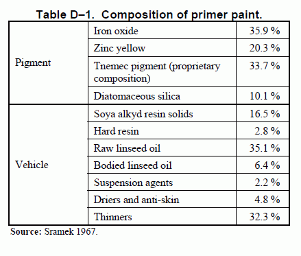
and the Material Safety Data Sheet (MSDS) for Tnemec's Series 010 Red Primer http://www.tnemec.com/resources/product/msds/m10v.pdf and http://www.tnemec.com/resources/product/MSDS/F010.pdf show that the composition is

picture.php


We can see that the above XEDS spectrum for the red layer of the MEK chip shows sufficient data to suggest that the material may contain

Talc - Mg3Si4O10(OH)2
Zinc Yellow - ZnCrO4

as well as the common oxides, aluminates and silicates.

I've shown in other posts on other threads how the platelets in Fig 8 and 9 have a large probability of being Kaolinite. Talc on the other hand has a different structure and XEDS data will show a different spectra too.

In order for the MEKS chip to be accepted as part of the data set of samples a) to d), these anomalies must be sorted out. The quickest way of doing this is to examine the MEK chip in the same detail as samples a) to d) - specifically looking at the morphology of the various particle structures and then performing XEDS on each particle to rule out talc as an a component of the red layer. Similarly ZnCrO4.

My subsequent General characterisation shows that samples a) to d) can be treated as one set, however, "sample Fig 31" cannot be part of that set and nor can the MEK chip which looks increasingly like it has a form of paint separate to the paint observed on chips a) to d). In effect there are 3 different samples in this paper, all of which were extracted using the same method, all of which are claimed to be thermite. I've shown that cannot be possible.
 
Searching for differences between questioned and known samples is the basic thrust of forensic paint analysis and comparison. However, differences in appearance, layer sequence, size, shape, thickness, or some other physical or chemical feature can exist even in samples known to be from the same source.

Jones' chips shpw spme variation in color and composition and structure. This is consistant with paint, according to the FBI standards.

Thermite, an engineered product, needs to be uniform in structure and composition to work.

The chips are, thus, in at least this aspect, more paint-like than thermite-like.

And it just occured to me that we may be making an error in assuming that all red paint chips are structural steel coatings. Think metal furniture.
 
.

And it just occured to me that we may be making an error in assuming that all red paint chips are structural steel coatings. Think metal furniture.

This is a good point. Dr. Greening at first seemed to be critical of the JREF thread because it was focusing on paint, but (correct me if I'm wrong) he also started making references to red primer!

My question still is how to explain the fact these little chips turned up in so many dust samples - in my view this would indicate they were a very common material in the towers. Paint still seems the most likely candidate for that reason as well....

Another curiosity is that Jones' paper doesn't indicate the presence of actual WTC paint remnants - this is remarkable. Wouldn't we expect to see at least SOME paint?
 
If you read my 3 large posts you'll see that I allude to the fact that the samples in Jones paper are not all one and the same and also that they can't all be from the same source.

There are literally thousands of sources for paint in NY. The only thing that makes me think that samples a) to d) came from the WTC buildings is that samples a) to d) match and they were found in 4 separate places.

I have no idea why they didn't screen for paint during characterisation of samples removed from the dust samples. Maybe they did but they don't say.
 
I point out again that DSC in an air stream will show combustion. The peak could be the carbonaceous binder burning in air. Thermite is a redox reaction and to show anything like it would require DSC in an inert stream, such as Argon.
 
Back
Top Bottom