Merged Discussion of femr's video data analysis

Correct.

The rest of your post is simply further demonstration that you don't understand.

I asked you a very simple question to try and help you without mocking you too much (which you chose to ignore in your continuing cherry-picking in responses)...

The simplest of examples...

1) Bank an aicraft model 90 degrees "left".
2) Increase vertical aircraft fuselage orientation.

In what direction does the tail of the aircraft move from your perspective ?

Up, down, left or right ?


Your answer really should make something "sink in". If it doesn't, or you get it wrong...

Answer the question, and get it right. You're going to great lengths to dig yourself a hole. I keep local copies of discussion images, so deleting them your end later doesn't erase them from existence.


The tail will move left. That is, of course, not how you do it. The trajectory and aircraft orientation in the NIST reports are relative to the building. Did you really roll the aircraft 38° and then apply pitch and yaw changes relative to the aircraft? No wonder your figures are so far out.

Also, as you obviously don't understand, and you're completely deaf to any advice, perhaps you'd care to measure (accurately!) a pertinent angle from your revered NIST...

[qimg]http://femr2.ucoz.com/_ph/2/2/495145715.jpg[/qimg]

Have fun. Stop digging the hole deeper.

Already measured, it's 10° as used in their impact analysis (13° trajectory, 3°left yaw). If you also care to measure their pitch angle you'll find it's 5°.
 
The tail will move left.
Correct !

That is, of course, not how you do it.
:( Incorrect.

The trajectory and aircraft orientation in the NIST reports are relative to the building.
:( Incorrect.

Orientation is, of course, relative to aircraft.

You've just done the learning curve by getting the question above right man !

Did you really roll the aircraft 38° and then apply pitch and yaw changes relative to the aircraft?
Of course !

No wonder your figures are so far out.
:jaw-dropp Deary me.

Already measured, it's 10° as used in their impact analysis (13° trajectory, 3°left yaw). If you also care to measure their pitch angle you'll find it's 5°.
:jaw-dropp Ye gads man.

Stop digging the hole.

I've checked the NIST orientation myself, using their values and rendered views...

196750867.gif


I'm correct. Hell, forget me, YOU answered my question above correctly.
 
Orientation is, of course, relative to aircraft.

So you believe that NIST thinks the aircraft was heading in at a trajectory 13° off perpendicular to the building face and with a dive angle of 6° and then had, separately, a 12° yaw relative to the aircraft's horizon which is now rolled 38° to the left.

Maybe you should look at figure 7-1 in NCSTAR 1-2b (page 158) or table 7-4

If you want to check your model, roll is the last thing you apply. Pitch and yaw values can be applied in any order but they must be done before roll is added.
 
So you believe that NIST thinks the aircraft was heading in at a trajectory 13° off perpendicular to the building face and with a dive angle of 6° and then had, separately, a 12° yaw relative to the aircraft's horizon which is now rolled 38° to the left.
Separately ? You're implying "additionally". In that case, no !

Maybe you should look at figure 7-1 in NCSTAR 1-2b (page 158) or table 7-4
Maybe you should read the rest of the report.

You'll find that NIST vary their frame of reference in various areas of the report, probably depending upon who wrote that bit, and when.

In Table 7-3 you'll find...

Lateral Fuselage Orientation from Structure North - 8° ± 6° clockwise from Structure North

In Figure 7–10 you'll find...

Baseline orientation and trajectory of UAL 175 from video analysis.

...on a static image (implying, as refernced elsewhere in the report, that orientation was aligned with trajectory for the simulations)

In Table 7-4 you'll find...

Lateral Fuselage Orientation Relative to Trajectory - -3° clockwise from lateral approach angle

In Figure 7–11 you'll find...

An orientation and trajectory of UAL 175 that matches the impact pattern
(vertical approach angle = 6°, lateral approach angle = 13°).


...again on a static image. Exactly what the orientation in that figure is cannot be easily determined, as the camera viewpoint is not orthagonal.

In Figure 7–12 you'll find...

An orientation and trajectory of UAL 175 that matches the impact pattern
(vertical approach angle = 6°, lateral approach angle = 17°).


...again, as above.


...and many other values, including...

Vertical Fuselage Orientation Relative to Trajectory - 1° nose-up from the vertical approach angle

...which has direct implication to aircraft axes, including roll.

What you will also find as you dig deeper, is...

923000555.png


...separated specification of orientation pitch/yaw from trajectory pitch/yaw.

I'll also dig out the details which suggest (as It's far from clear, as I noted in my draft from 3 years ago) that NIST aligned trajectory with orientation within the actual impact simulation...further muddying the waters.

If you want to check your model, roll is the last thing you apply. Pitch and yaw values can be applied in any order but they must be done before roll is added.
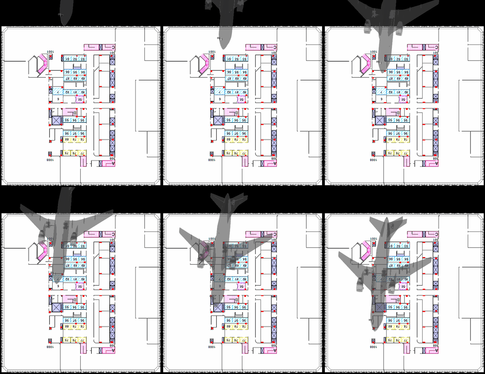
The problem you have ther is, as I really tried to hint to you above with the little animation...I have CHECKED the orientation of the aircraft from the NIST provided top and side views of the moment of impact.

A moral: What NIST say, and what NIST actually DO are not always exactly the same thing.

If I go to the bother of regenerating the imagery required to prove what orientation NIST used...
495145715.jpg

...are you going to waste even more of my time disputing it ?

If so, do it yourself.

You'll need to use BOTH the top and side views. If you dit it, do it properly. You really should use a 3D modeling environment, a-la...
196750867.gif
 
.
923000555.png


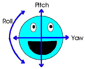
pitchyawroll.GIF

Pitch= up/down angle
Yaw= left/right angle

Trajectory (or approach)angle = direction of motion, along the flight path of the airplane, not the same as:
Orientation angle= center line axis of fuselage, shown as the still images at impact.

NIST Base Case ; Orientation- pitch 5.0 deg up , Orientation –yaw 10 deg left. These are the proper NIST angles to model the plane at the point of impact, from the stills, just based on this chart.

You can see the difference between trajectory(or approach) and orientation here:


Once this difference is understood, the NIST numbers match.
 
Last edited:
Femr is using a 13° yaw figure for his NIST orientation. If you place the centreline of the aircraft at the impact point and rotate the fuselage in the x plane until you hit 13° and then move the centreline of the fuselage up in the y plane to get the 6° pitch angle the yaw angle doesnt change when viewed from above (unless you place your camera close and still have perspective view on which you obviously wouldn't to get a true plan view). As can be clearly seen the top of the fuselage (which is parallel to the aircraft centreline) should match a 13° line. Rotation of the fuselage will similarly have no effect on on perceived yaw angle when viewed from directly above.

Y'know, I would have said that the NIST report never uses "yaw" to refer to comparisons with Structure North, but then I searched the PDF and found the table in executive summary, which femr2 subsequently posted. Obviously I was using "yaw" in the pen's frame of reference.

I think we all agree that NIST in chapter 7 ultimately puts the plane at a trajectory of 13° clockwise from Structure North, and an orientation of 10° clockwise from Structure North. These angles can even be measured off Figure 7-13 (by running a line through the center of the plane).
 
Y'know, I would have said that the NIST report never uses "yaw" to refer to comparisons with Structure North, but then I searched the PDF and found the table in executive summary, which femr2 subsequently posted. Obviously I was using "yaw" in the pen's frame of reference.
NIST vary their frame of reference within the report.

From the research carried out 3 years ago, there is a reference in the report somewhere which indicates that a simplifying step of aligning orientation with trajectory was performed, but I'll be damned if I can find it right now.

Until I can, I'm forced to state that visual representation of the NIST aircraft within my study does not match the parameters discussed...as in it's wrong. However, that doesn't affect the orientation of the femr2 aircraft, nor the rotoscoping performed.

Perhaps the reason for the (currently not refound) indication for the mentioned alignment was that inconsistency in frame of reference.

It's pretty unusual (at best) to specify yaw and pitch of a banked aircraft using a frame of reference other than the aircraft ! :eye-poppi

Who knows, unless I find that darn reference. If I misinterpreted the frame of reference three years ago...so be it. Changing that would move the NIST orientation in rotoscoped view closer to "actual", but not exact. Less wrong.

I think we all agree that NIST in chapter 7 ultimately puts the plane at a trajectory of 13° clockwise from Structure North
Sure, though remember that the point of all this is to highlight the actual aircraft orientation and trajectory.

and an orientation of 10° clockwise from Structure North. These angles can even be measured off Figure 7-13 (by running a line through the center of the plane).
As I suggested to Reactor Drone, the various images in the report can be used to verify orientation. The results are surprising, though I really can't be bothered to do the leg work at the mo.

I'll get around to locating the reference mentioned, but until then...again, NIST aircraft orientation in my old study does not match a 10/5 orientation from structure north.

NIST is still off, of course ;)
 
Pitch= up/down angle
Yaw= left/right angle
:rolleyes: The correct frame of reference for pitch and yaw of an airccraft is the aircraft.

Once this difference is understood, the NIST numbers match.
As I've said, I need to find the NIST reference mentioned...however, NIST numbers still don't match. With different frame of reference, closer, but still off.
 
...Sure, though remember that the point of all this is to highlight the actual aircraft orientation and trajectory...
Yes - plus changing the topic focus from WTC 7 measurement accuracy - plus the effect of meteorological conditions affecting this topic.

There are still some aspects I have parked on a back burner - temporarily. :)

Mostly in the area of legitimate "so what?" :rolleyes:
 
Yes - plus changing the topic focus from WTC 7 measurement accuracy - plus the effect of meteorological conditions affecting this topic.

Now that we've established the cause of the problem with femr2's aircraft orientation this little sidetrack is pretty much done and you can get back to counting the angels on the head of the pin.
 
Mostly in the area of legitimate "so what?" :rolleyes:

None of this (aircraft impact) discussion has been framed (not my favorite word at the mo) by implications of such. It's all "prove femr2 wrong version the umpteenth" type. Must find that darn reference at some point ! :boggled: But until then there's no issue "fessing" to an interpretation error, and it wouldn't change my own results, so no worries ;)

From my perspective getting the impact right is a "key" step in the simulation, as by direct implication it affects all that follows.

As I have previously stated, it is my opinion that the actual impact trajectory and orientation would likely have resulted in more damage to more of the first two core column rows, certainly more evenly towards the North side...which could aid understanding of subsequent perimeter behaviours such as IB.

I'm amazed that there now exists a couple of 7 foot tall plywoord tower "replicas" though. (Though no confirmation of that unfortunately). Wow :) I wonder if Reactor Drone feels like setting up a filament cradle for the aircraft model (glued with dihedral wing angle by application of weights during construction) so that it can be filmed impacting the towers ;)

ETA: And for historical accuracy...the actual reason for any of the impact parameter studies were claims that both the Carmen Taylor and Hezarkhani footages were "faked" due to their perspective being "impossible". Needless to say none of the voices here complained that the study proved such claims wrong, yet when NIST was criticized... :)
 
Last edited:
Now that we've established the cause of the problem with femr2's aircraft orientation
:rolleyes: None of the above affects the femr2 aircraft orientation. All it is is an error (until I find the reference mentioned) with the NIST aircraft orientation in my rendered views. Annoying, but no biggie. Would bring NIST closer is all.
 
:rolleyes: None of the above affects the femr2 aircraft orientation. All it is is an error (until I find the reference mentioned) with the NIST aircraft orientation in my rendered views. Annoying, but no biggie. Would bring NIST closer is all.

If you used the same method to orient and measure both aircraft then the error will be present in both. Your 3.5°, 3° orientation is using a completely different co-ordinate system to the NIST report and so can't be directly compared. You'd need to translate to the same co-ordinate system to compare values.
 
None of this (aircraft impact) discussion has been framed (not my favorite word at the mo) by implications of such. It's all "prove femr2 wrong version the umpteenth" type. Must find that darn reference at some point ! :boggled: But until then there's no issue "fessing" to an interpretation error, and it wouldn't change my own results, so no worries ;)...
I tend to keep the objective or topic in focus and try to avoid the changes of direction which are not the consequence of legitimate discussion. In that context the OP was interesting - a quite positive move by tfk to discuss the accuracy of your analyses. He only mentioned one specific - sub-pixel resolution - and that one was much clarified within the first few pages of the thread. Believe it or not it was ~2.5 years back. How time flies when we're having fun.
...From my perspective getting the impact right is a "key" step in the simulation, as by direct implication it affects all that follows...
Understood.
...As I have previously stated, it is my opinion that the actual impact trajectory and orientation would likely have resulted in more damage to more of the first two core column rows, certainly more evenly towards the North side...which could aid understanding of subsequent perimeter behaviours such as IB...
Agreed but the consequences and implications go beyond this topic.
...I'm amazed that there now exists a couple of 7 foot tall plywood tower "replicas" though. (Though no confirmation of that unfortunately). Wow :) I wonder if Reactor Drone feels like setting up a filament cradle for the aircraft model (glued with dihedral wing angle by application of weights during construction) so that it can be filmed impacting the towers ;)...
You will remember this one. Some of the members here may not be familiar with it - the builder did not last long here at JREF.
...ETA: And for historical accuracy...the actual reason for any of the impact parameter studies were claims that both the Carmen Taylor and Hezarkhani footages were "faked" due to their perspective being "impossible". Needless to say none of the voices here complained that the study proved such claims wrong, yet when NIST was criticized... :)
As far as I am aware lèse majesté is no longer a capital crime in any of the relevant jurisdictions. ;)

Let me prove it:

NIST was wrong on some details. <<<Ozeco41 said that.
AND
Bazant was wrong on some things. <<<Ozeco41 said that too.

..if I don't return to this forum and you read my obituary 'struck down by a god' you will know I was wrong... :rolleyes:
 
Changing that would move the NIST orientation in rotoscoped view closer to "actual", but not exact. Less wrong.
Not exact?

Whose orientation is exact?

Yours certainly isn't.

What was the exact orientation? Do you know?

You keep dealing with this as if your orientation is right and NIST's is wrong. That's false and misleading. You can claim to achieve better precision than NIST's but not any wrongness on NIST's orientation. Again, it's a precision question.
 
Your 3.5°, 3° orientation is using a completely different co-ordinate system to the NIST report
As I've said NIST use varying frames of reference, which include that of the aircraft.

You'd need to translate to the same co-ordinate system to compare values.
Not a problem. Quick measurement from images provided...

~6 degrees lateral from structure North.

~2.5 degrees vertical fuselage orientation below horizontal.
 
Not exact?
Aiii.

Whose orientation is exact?
Noone's.

Yours certainly isn't.
Didn't say it was.

What was the exact orientation?
Close to mine.

Do you know?
I know it's close to mine, yes.

You can claim to achieve better precision than NIST's
Indeed.

but not any wrongness on NIST's orientation
Of course I can, even via my own personal view of how far out they have to be for wrong to be relevent. You'll have noticed I frame "wrong" quite fairly most of the time.

it's a precision question.
And ?
 
femr2:

NIST obviously used the aircraft's flight path combined with orientation at impact to try to determine the extent of damage to the building. (that's how they got yaw and pitch). They did not use the orientation to determine the flight path.

How does the damage differ if you use your orientation this way? Just curious.
 
How does the damage differ if you use your orientation this way? Just curious.
The trajectory and orientation are effectively indistinguishable from each other...a separate chunk of study.

As I'm sure you know full well, a simulation would need to be re-run to state opinion about damage changes forcefully, however, I've given my opinion just a couple of posts ago ? Did you miss it for some reason ?

From my perspective getting the impact right is a "key" step in the simulation, as by direct implication it affects all that follows.

As I have previously stated, it is my opinion that the actual impact trajectory and orientation would likely have resulted in more damage to more of the first two core column rows, certainly more evenly towards the North side...which could aid understanding of subsequent perimeter behaviours such as IB.

From 3 years ago...
image083.gif


Needless to say the decision by NIST to SET lateral trajectory to 13 degrees almost solely on assumption of a linear path between engine entry point and NE corner of the building wasn't a good one...a decision shown to be quite flawed due to studies provided by both myself and achimspok, and the angle between the NE corner and the engine resting point (~20 degrees).

Obviously now that focus appears to be, er, heading to trajectory...it should be noted that even with restating the femr2 orientation relative to the building (ew) there's still around 100% error in NIST lateral value for trajectory which remains set at 13 degrees.
 
You will remember this one.
Ba-doing :)

Perhaps it would be useful to trace subsequent oscillations...
468976343.png

...which can be done spectacularly acurately using the sub-pixel methods and procedures previously discussed. Indeed with a much lower noise level than even the NIST moire method, as also previously demonstrated.

I'm joking about tracing the ba-doing, of course. You can never be too sure roun'ere :)
 

ISF - Join now!

Every member here is approved by hand. No bots, no spam, just people who care about evidence and honest debate.

Membership is free!

Create your free account

Back
Top Bottom