• Quick note - the problem with Youtube videos not embedding on the forum appears to have been fixed, thanks to ZiprHead. If you do still see problems let me know.

WTC7 and the girder walk-off between column 79 and 44

Status
Not open for further replies.
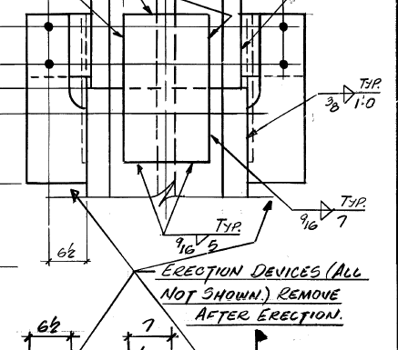
A couple of quick sketches for those who'd like to see how the column splices work.

This was in response to Tony's assurance that the splice joints would provide just as much stiffness & resistance to buckling (i.e., equivalent MoI) as would a continuous, unbroken beam. An assumption that was integral to his calculations about how much the column would deflect in response to side load, and to his calculation as to how many stories of column 79 would have to be unsupported before it went unstable.

Tony's assurances turn out to be false. Numbers below.

First sketches:
Note: all components drawn to scale.

Isometric view of splice joints & seats.
[qimg]http://www.internationalskeptics.com/forums/picture.php?albumid=553&pictureid=6214[/qimg]
[Note: bolts exploded for clarity]

Top view of splice joints & seats
[qimg]http://www.internationalskeptics.com/forums/picture.php?albumid=553&pictureid=6215[/qimg]
[Note: seat on south side of column not shown.]

Calculation of Moment of Inertia of built-up column versus bolts

Component|I|A|d|n|Itot
||(in^2)|in||(in^4)
Column|4715|214.5|0|1|4715
Side plates|16.3|48.8|9.95|2|9679
Total|||||14394
|||||
Bolts|0.05|0.7854|17.45|8|1913
|||||
|Values verified|||Ratio (beam/bolt)|7.5
MoI calculated for deflections in east-west direction, i.e., "about vertical axis of top view thru center of column"


Observations

1. The splice plates are incredibly thin. The MOI calculation assumes that they will stay straight & untorqued when side load applied. This assumption seems wildly optimistic to me.

2. From the table: The MoI's of the various components are calculated using the standard "parallel axis theorem". From the table, one can see that the MoI of the column is about 7.5x greater than the MoI of the 8 bolts.

3. MoI of joint to deflections in north south direction (about horizontal axis in top view) is pretty darn close to zero. The splice plates are simply going to torque, and the alignment plates, not being welded to upper column, provides zero recoverable strain, and therefore do not contribute to MoI.

4. The bolts are thermally isolated from the heat sinking mass of the columns. They are going to heat up & lose strength in a fire far faster than the columns themselves.

That's not completely accurate. The column will still provide compression resistance through part of the shape when the splice is subjected to bending. The calculation of MoI needs to follow something similar to how it is calculated in reinforced concrete.

It's not a simple calculation, however.
 
Where did you get the dimensions and configuration of the column splice you show? The NIST WTC 7 report doesn't give sizes and configurations of column splices.

However, the recently released drawings do, and the sizes and configuration you show aren't what is shown in the released drawings. The splice plates shown in the actual drawing are significantly larger than what you show.

"Significantly larger" doesn't help much. Which dimension do you think is off?

How did you determine the scale?

All dimensions taken right off of the Frankel drawings. Each part created from the drawings in a 3D CAD program.

I just check the splice plates & they are right on the callouts.

pc plate = 1" thick
pb & pbx plates = 0.5" thick.
 
That's not completely accurate. The column will still provide compression resistance through part of the shape when the splice is subjected to bending. The calculation of MoI needs to follow something similar to how it is calculated in reinforced concrete.

It's not a simple calculation, however.

You're right, this is a complicated calculation.

I was look looking at it from the perspective of traditional 2nd moment of area (which we've been calling MOI) calcs, which relate a bending load to generated stresses in the bent part. From this perspective, a fractured part will not generate any stresses in adjacent segments, the fracture simply opens up.

I realized that the compressive loads also generate a force on the mating column surfaces that resists lateral motion until the side load generates a moment that overcomes the compressive loads applied at the inner & outer fiber of the columns. But this also doesn't produce bending stresses in the column.

In order to produce bending stresses, the outer fiber of the column must go into tension across the cut. It just cannot do this DIRECTLY if the column is two parts.

But you've pointed out an additional constraint that allows this to happen indirectly: as long as the bolts, splice plates, welds, etc., are intact, and the compressive load is high enough [ETA] and the lateral loads low enough, then the two mating faces of the column will be constrained to remain approximately parallel to each other.

But it seems to me that, in this case, this is not equivalent to a continuous beam for 2 reasons.

1. The constraint is in one plane only. And maintained by long, slender splice plate webs, with non-axial applied loads.

2. The assembly is massively unstable to shear or off-axis loading.

First off, there is very little shear strength between the upper & lower columns at the interface. This has been reduced by a factor of about 40 (ratio of area of bolts to column area) in one axis, and a comparable amount (ratio of area of weld bead to column area) in the other axis.

Further, any slide slippage of the upper column with respect the lower one will allow the mating surfaces to disengage. As soon as any one corner of the upper column drops off of the mating corner of the lower, all bets are off. The whole column will simply fold at the interface.

Last, the side loads from girders c79/c44 & c79/c76 do not impart forces that are aligned with the column axes.
___

This splice joint is simply a bracket. A very light weight, thin walled bracket.

There was a much, much, much stronger bracket that kept the upper & lower column segments aligned to each other: the beam/shear studs/concrete composite floors, the other girders etc., all tied to each other & to the external frame of the building.

I look at the splice plates in just the same way that I look at erection bolts. It was a device to keep the components in alignment while that heavy duty bracket was being assembled (i.e., the concrete floors poured & set up).

There is no way that, once the heavy duty bracket was destroyed, the lightweight bracket going to be able to do the same job against lateral forces that were never envisioned being applied to this joint.
 
Last edited:
The building is already on its way down at that point. That says nowt about the condition prior to descent.

Then perhaps you should ask Chris7 why he presented this image as an argument for the building not tilting prior to collapse.

How exactly would NIST use their crappy moire technique, which only measures the motion of a single "point" (sort of), to determine leaning ? And where would that study be in the report ?

If that is your impression of moire, then you don't understand moire.

Moire depends on lines of approximately (but not exactly) parallel features in two separate components. The brightness of pixel columns on either side of the building's edge was a continuous, linear function down the side of the building. Therefore they were inherently measuring lean of the building.

From this leaning measurement, they reported lateral displacement of the upper corner.

But, of course, you're just about to say that "you knew that all along".
:rolleyes:

What do you think they call it if the top of a building moves sideways, while the foundation stays fixed in place?

Hint: Starts with an "L", and ends with an "ean".

Meanwhile, if you think that NIST's "crappy" Moire pattern cannot measure lateral displacement, then perhaps you can explain why you used NIST's "crappy" measure of lateral displacement as support for your measurement of lateral displacement.

You truthers gotta get your story straight.

You still haven't responded within the "NIST blew WTC7 Stage 1 analysis" thread you started.

Tell ya what. Why don't you state clearly what you think was the criteria that NIST used to determine their t0.

Can't wait to hear the excuses you're going to use to not say anything...
 
You're right, this is a complicated calculation.

I was look looking at it from the perspective of traditional 2nd moment of area (which we've been calling MOI) calcs, which relate a bending load to generated stresses in the bent part. From this perspective, a fractured part will not generate any stresses in adjacent segments, the fracture simply opens up.

I realized that the compressive loads also generate a force on the mating column surfaces that resists lateral motion until the side load generates a moment that overcomes the compressive loads applied at the inner & outer fiber of the columns. But this also doesn't produce bending stresses in the column.

In order to produce bending stresses, the outer fiber of the column must go into tension across the cut. It just cannot do this DIRECTLY if the column is two parts.

But you've pointed out an additional constraint that allows this to happen indirectly: as long as the bolts, splice plates, welds, etc., are intact, and the compressive load is high enough [ETA] and the lateral loads low enough, then the two mating faces of the column will be constrained to remain approximately parallel to each other.

But it seems to me that, in this case, this is not equivalent to a continuous beam for 2 reasons.

1. The constraint is in one plane only. And maintained by long, slender splice plate webs, with non-axial applied loads.

2. The assembly is massively unstable to shear or off-axis loading.

First off, there is very little shear strength between the upper & lower columns at the interface. This has been reduced by a factor of about 40 (ratio of area of bolts to column area) in one axis, and a comparable amount (ratio of area of weld bead to column area) in the other axis.

Further, any slide slippage of the upper column with respect the lower one will allow the mating surfaces to disengage. As soon as any one corner of the upper column drops off of the mating corner of the lower, all bets are off. The whole column will simply fold at the interface.

Last, the side loads from girders c79/c44 & c79/c76 do not impart forces that are aligned with the column axes.
___

This splice joint is simply a bracket. A very light weight, thin walled bracket.

There was a much, much, much stronger bracket that kept the upper & lower column segments aligned to each other: the beam/shear studs/concrete composite floors, the other girders etc., all tied to each other & to the external frame of the building.

I look at the splice plates in just the same way that I look at erection bolts. It was a device to keep the components in alignment while that heavy duty bracket was being assembled (i.e., the concrete floors poured & set up).

There is no way that, once the heavy duty bracket was destroyed, the lightweight bracket going to be able to do the same job against lateral forces that were never envisioned being applied to this joint.

In the case of the column, the stiffener (or a small part of the stiffener) near the bolt that resists the compression component of the moment across the splice will also act in compression. The stiffener on the other side won't provide any resistance at all. This type of behavior is well understood and developed for concrete beams with reinforcement on both top and bottom. I'd give you the equations, but I don't have my books with me at the moment and I really don't want to derive them. :p

I also see a plate connecting the flanges of the two columns. If it is welded to the top and bottom column then it may provide some additional stiffness.

Another thing:

The column splice cannot develop the full bending moment of the column. In the NIST anaylsis, the column may be under horizontal loads that yield (but doesn't fracture) the column splice. This type of behavior is something that Mr. Szamboti routinely neglects in his incorrect back-of-the-envelope checks.
 
Then perhaps you should ask Chris7 why he presented this image as an argument for the building not tilting prior to collapse.
Why not ask yourself why you'd not point it out yourself.

If that is your impression of moire, then you don't understand moire.
L.O.L. Oh dear.

Moire depends on lines of approximately (but not exactly) parallel features in two separate components. The brightness of pixel columns on either side of the building's edge was a continuous, linear function down the side of the building. Therefore they were inherently measuring lean of the building.
Nope. They were using the fact that the viewpoint was off axis. The resulting data didn't really show lean, it showed twisting, flexure. It may even have been the effect of wind unitl immediately prior to descent.

From this leaning measurement, they reported lateral displacement of the upper corner.
Chortle. Where ?

But, of course, you're just about to say that "you knew that all along". :rolleyes:
Nope. They measured sub-inch resolution flexure of the building consistent with flexure, not leaning. A measure of leaning would require additional information not determinable from a single point, as I said earlier to you before you, er, responded.

You can be pedantic and suggest that flexure is a form of leaning, but that's not really what you meant, is it :)

What do you think they call it if the top of a building moves sideways, while the foundation stays fixed in place?
Flexure.

Are you suggesting that a couple of inches of movement in a tall structure is indicative of that structure failing ?

Excuse the pun, but this door swings both ways Tom :)

Hint: Starts with an "L", and ends with an "ean".
Barrel scrape fail.

Meanwhile, if you think that NIST's "crappy" Moire pattern cannot measure lateral displacement
In which direction ? :) Twisting. Flexure. Any other words you'd like to show your assertion a little, er, premature ? With which addition point was "lean" determined ?

then perhaps you can explain why you used NIST's "crappy" measure of lateral displacement as support for your measurement of lateral displacement.
Because I wouldn't misinterpret the motion so ineptly. Have said lord knows how many times that I suggest it's a flexure-type motion, and certainly have not suggested that it suggests any kind of lean.

Barrel scrape fail again.

Tell ya what. Why don't you state clearly what you think was the criteria that NIST used to determine their t0.
ROFL. I'll tell you EXACTLY :)

How about...
NIST T0 Selection

By usage of the brightness profile in NIST Figure 12-75 the exact pixel and (interlaced) frame that NIST selected was determined...


Source Video | CBS-Net Dub7 47.avi (RAW NIST FOIA - 1Gb DV File)
Pixel | 304, 171
Frame | 5398

That point is the exact start of the NIST Stage 1.

It is also ~6s after the start of the East Penthouse descent.

The following graph shows motion of the NW corner relative to the NIST T0 and their East Penthouse release time...


As you can see, relative to NW corner motion, the NIST T0 looks pretty meaningless.

The NIST release time for the East Penthouse is also inaccurate, but that's not relevant for this thread. (It's much closer to exactly 6s prior to their T0).


NIST chose that spot with the assumption that detected motion after that point in time was vertical. In fact that motion is initially primarily North->South, as the formation of the "kink" was misinterpreted by NIST to be vertical in nature.

If they had compared the roofline profile of their chosen Cam#3 viewpoint...

...against that seen from the Dan Rather viewpoint...

...it would have been obvious that the "kink" was formed primarily North->South.

There are other ways to prove such, but comparison of the two images above (which are synchronised at the same point in time) is by far the simplest way to present the NIST interpretation error.

So, the start point of NIST "Stage 1" is, at best, flawed.
...from the thread you seem to steadfastly refuse to address, even though you are the OP :confused:

Can't wait to hear the excuses you're going to use to not say anything...
Really ?
 
Last edited:
"Significantly larger" doesn't help much. Which dimension do you think is off?

How did you determine the scale?

All dimensions taken right off of the Frankel drawings. Each part created from the drawings in a 3D CAD program.

I just check the splice plates & they are right on the callouts.

pc plate = 1" thick
pb & pbx plates = 0.5" thick.

What is the Frankel drawing number you got these dimensions from?
 
Last edited:
Newt,

Here's a better image, with labels.
(Labels match Frankel drawing #1091.)
picture.php


In the case of the column, the stiffener (or a small part of the stiffener) near the bolt that resists the compression component of the moment across the splice will also act in compression.

By "stiffener", I think that you mean the 2" thick plate that is welded to the flanges of the I beam, labelled "pa / paa". Correct?

Yup, but not anywhere near the same amount of compression that a continuous beam will generate when bent.

In bending, the tension in the outer fiber & compression in the inner fiber act as mutually supporting, mutually generating pairs. Without either one, you can't get the other.

As you say, tho, there will be a shift of the gravitational load from "distributed evenly over the mating surface" to "concentrated on the compression edge".

The stiffener on the other side won't provide any resistance at all.

Resistance to opening up the split (i.e., tension). Agreed.

And the same (i.e., "no resistance" = "no contribution to bending resistance") applies to both tension & compression generated by any fibers throughout the thickness of the beam, except for the gravitational compression of the innermost fiber of the side plate.

This type of behavior is well understood and developed for concrete beams with reinforcement on both top and bottom. I'd give you the equations, but I don't have my books with me at the moment and I really don't want to derive them.

Interesting. I'm not seeing exactly what you're describing.

I also see a plate connecting the flanges of the two columns. If it is welded to the top and bottom column then it may provide some additional stiffness.

True. I think you're referring to plate "pd". It is described as welded to the column on the lower half, but there is not note that I've seen regarding welding to the upper beam after they've been joined.

I'd be interested to know if anyone knows whether this is shown welded to the mating beam in any shop drawings.

Without an upper weld, this column (even with the bolted splice plates) is extremely weak in bending as pushed by the c44-c79 girder (shown as a short stub of the whole girder in cyan with magenta stiffener plate).

The column splice cannot develop the full bending moment of the column. In the NIST anaylsis, the column may be under horizontal loads that yield (but doesn't fracture) the column splice. This type of behavior is something that Mr. Szamboti routinely neglects in his incorrect back-of-the-envelope checks.

Agreed.
 
Last edited:
Hah, I should call it a built-up flange, not a stiffener :D

S'all right.

What you meant was (pretty) clear by what you said.

It had the distinctive advantage of "making sense in context".

Sometimes that's in short supply 'round these parts.
 
Newt,

Here's a better image, with labels.
(Labels match Frankel drawing #1091.)
picture.php


By "stiffener", I think that you mean the 2" thick plate that is welded to the flanges of the I beam, labelled "pa / paa". Correct?

True. I think you're referring to plate "pd". It is described as welded to the column on the lower half, but there is not note that I've seen regarding welding to the upper beam after they've been joined.

I'd be interested to know if anyone knows whether this is shown welded to the mating beam in any shop drawings.

Detail at Dwg E118A bottom right 2nd from bottom shows (13th floor floor)
"Core column grid 79 at ....13th... flrs" shows the col. flange side plates pa/paa welded at the splice and pd welded at top col.
Also I believe pb and pc were temporary lifting plates removed after installation.
The columns were two stories tall. Their splices at 11th , 13th, 15th floor floors.
 
Last edited:
...It had the distinctive advantage of "making sense in context".

Sometimes that's in short supply 'round these parts.
thumbup.gif

I think I made that comment a couple of times.....

.....something about unproven assumptions of context.

By someone who proceeded to build a "house of cards" argument based on that unproven assumption.
 
Last edited:
thumbup.gif

I think I made that comment a couple of times.....

.....something about unproven assumptions of context.

By someone who proceeded to build a "house of cards" argument based on that unproven assumption.

Who did you have in mind.
 
Guys.........great discussion!

It's nice to watch people who are knowledgable in a field discuss details and have a back and forth discussion on the specifics.

Too bad the truthers can't contribute much..........but no matter..........for those of us in other Engineering fields.....it's nice to watch.

Keep up the great work!

When I see rationalists having a discussion, there is usually positive motion, reminding me of the March of Progress evolution cartoons....

But watching Truthers "debate" and discuss is like watching Brownian Motion.

"Round and 'round she goes,
Progress is for Shmoes."

:D
 
Status
Not open for further replies.

Back
Top Bottom