• Quick note - the problem with Youtube videos not embedding on the forum appears to have been fixed, thanks to ZiprHead. If you do still see problems let me know.

WTC7 and the girder walk-off between column 79 and 44

Status
Not open for further replies.
No facts or data

No substance

No rebuttal

Just Endless questions and gibberish:
"did you check the point on the central web co-linear with the top of the stiffener plate ... ?"

And that is "gibberish" devoid of "substance" because...?

Because anything you don't understand must not mean anything?
 
Just Endless questions and gibberish:
"did you check the point on the central web co-linear with the top of the stiffener plate ... ?"

Apparently engineering and math is "gibberish" to Sarns.....:rolleyes:although this is no surprise.....we already knew this.;)

Stop confusing the truthers with engineering and math Tom! :confused:

That stuff is "gibberish".....maybe you should make a youtube video...
 
These calculations were done by a structural engineer named Ron Brookman and he has sent a letter to the NIST about it. I don't have a copy of his calculations so I did them here myself to prove to those of you here that what Gerrycan said in his video was correct on this issue. That is that the stiffener would take the vertical load, once the web was beyond the seat, and prevent the flange from folding.

The load I used was based on the 53 x 45 foot area to the east of the girder and 10% of the area west of it. I looked at the west side area in the NIST report and the girder in question only carries one short beam from that area with the six longer beams of that area going to the girder between columns 76 and 79. Bear in mind that each girder support carries 25% of the loads of an area as there are three other supports. So the area is approximately equivalent to 27.5% of the area to the east x 125 psf which is 75 psf dead load and 50 psf live load. The load is thus 53 x 45 x 125 x 0.275 = 81,984 lbs.

The stress is a combination of bending stress and shear stress on the weld between the stiffener and parent material of the girder.

Bending stress = MY/I where the bending moment (M) equals the distance from the web to the center of pressure on the flange multiplied by the load. Y is the distance to the neutral axis and would be the midpoint of the weld length and flange thickness = (0.855" + 18")/2 = 9.428". I is the moment of inertia and is equal to the height of the weld cubed divided by 6 for a double sided weld. So (18^3)/6 = 972 in^4.

The moment is 81,984 lbs. x 4.5 inches = 368,928 inch lbs., and the bending stress is (368,928 x 9.428)/972 = 3,578 psi, when the web is 3.5 inches past the seat and the center of pressure on the flange is 4.5 inches from the web.

The shear stress is just force/throat area. The 5/16" fillet weld is on both sides of the stiffener so throat area is 2 x 0.707 x 0.3125" x 18" = 7.954 sq. inches. The shear stress is 81,984 lbs./7.954 sq. inches = 10,308 psi.

The resultant stress = sqrt[shear stress^2 + bending stress^2] = 10,911 psi.

The weld was made using E70 weld metal, which has a tensile yield strength of 58 ksi and a shear yield strength of 0.577 x 58 ksi = 33.4 ksi.

The factor of safety would be 33,400/10,911 = 3.0, so this weld would certainly stay put and keep the flange from folding while the girder web was moved beyond the seat.

This means the girder would not fall off the seat until it was pushed at least 9.5" to the west, due to the girder having these 18" tall flange stiffeners. It has already been shown that the maximum westward expansion of the beams to the east, at any temperature, was 4.75".

This shows the alleged walk-off failure was impossible and the NIST needs to put these stiffeners in the report and correct their analysis.


Ahh that explains a lot. you are just parroting someones else work. This is a gross oversimplification of the problem. For example I see no account is taken of the beam twisting as its loading moves off its central axis nor do I see any account taken for the high temperatures involved and their effects on the materials used. Add in the possible movements of every other beam in that area of the building and one cannot say with any confidence that the beam cannot have failed at that joint.

NIST may not be 100% correct in there analysis and I don't think they claimed they were but its a huge leap to suggest that therefore the building cannot have failed due to fire. Some systems are just too complex to be able to model with 100% accuracy. NIST found what they considered the most likely cause of the failure and given that they are better qualified and did a lot more work on this than anyone else I see no reason to doubt that they are probably close to being right.
 
Tom, you shouldn't forget that drawings which revealed certain details of the girder connection, like the 12" wide seat, the 2" thick x 14" deep x 18.875" wide plate pg under the seat, and the 3/4" thick x 5.5" wide x 18" tall flange stiffeners on the girder, were only recently released.

With these details known and factored into the analysis, it is now clear that a walk-off failure of the girder between columns 44 and 79, under the 13th floor in the northeast corner of WTC 7, was impossible, and the NIST needs to correct their analysis and the report.

Fine, then what? Building still collapsed due to fire, even if NIST never could prove how this happened, it would alter nothing. No one of any import is going to start thinking it was CD because an engineer can't prove how fire brought down a building :rolleyes:
 
Ahh that explains a lot. you are just parroting someones else work. This is a gross oversimplification of the problem. For example I see no account is taken of the beam twisting as its loading moves off its central axis nor do I see any account taken for the high temperatures involved and their effects on the materials used. Add in the possible movements of every other beam in that area of the building and one cannot say with any confidence that the beam cannot have failed at that joint.

NIST may not be 100% correct in there analysis and I don't think they claimed they were but its a huge leap to suggest that therefore the building cannot have failed due to fire. Some systems are just too complex to be able to model with 100% accuracy. NIST found what they considered the most likely cause of the failure and given that they are better qualified and did a lot more work on this than anyone else I see no reason to doubt that they are probably close to being right.

No, I did not parrot somebody else's work. You should try reading my first paragraph prefacing the calculations a little harder. I explained that Ron Brookman had done calculations and sent a letter to the NIST, but I don't have his and did my own, which turned out to show the same end result.

You have a lot of nerve trying to impugn me when we haven't seen you do a single calculation.
 
Last edited:
Tony,

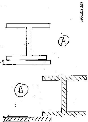
You'd make your prose a lot easier to follow if you were to supply a quick sketch, showing forces, moments, & identifying where you are trying to calculate stresses. You know, like people supply when they are trying to explain their stuff clearly.
___

And your explanations leave a lot to be desired.

For example, please explain how you got inches4 out of this calculation:


It doesn't help your credibility to leave out dimensions & inexplicably change inches3 into inches4.

Without a diagram, it's tough to tell what you are calculating here.

For calculating MOI of a weld it is treated as a line with no width and so the length or height of the weld is cubed as it is for a prismatic beam with (bh^3)/12 but no b term. The 6 is in the denominator here is due to there being two welds.

The units resulting from MY/I here should be lbs./inch not psi.

So a correction to the above would be the bending load is 3,578 lbs./inch. The shear load can also be calculated in lbs./inch by considering only the length of the weld, and it would be 81,984 lbs. / (2 x 18 in.) = 2,277 lbs./inch.

The resultant is sqrt[2,227^2 + 3,578^2] = 4,241 lbs./inch.

Stress = resultant/(0.707 x weld size) so 4,241 / (0.707 x 0.3125) = 19,195 psi. The factor of safety would be 34,000/19,195 = 1.77. This is for the girder web moved 3.5 inches past the seat where it would have been pushed 9.545" and the center of pressure at 4.5 inches from the web.

If the girder was pushed 8.545 inches and the center of pressure on the flange was 4 inches from the web the result would be 16,846 psi and a factor of safety of 2.0.

The above are for full live loads. If we do the calculations for a 50% reduced live load (100 psf full load) the load on the girder support at column 79 becomes 65,588 lbs. and the stress with the girder pushed 9.545 inches is 15,359 psi and the factor of safety is 34,000/15,359 = 2.21. At a push of 8.545 inches the stress and factor of safety are 14,165 psi and 2.40, respectively.

I don't think there is any doubt this girder could have been pushed at least 8.5 inches without falling. This pretty much proves the NIST theory for collapse initiation was impossible. Of course, there will probably be some here who will attempt to say we can't know as everything was in a state of flux and what not, but that is nothing more than hand waving nonsense. Real effects require real causes and the NIST story does not have one.
 
Last edited:
And that is "gibberish" devoid of "substance" because...?

Because anything you don't understand must not mean anything?
Chris-"It's all Greek to me"-Sarns, has already admitted he doesn't understand the simplest of equations, he's just interested in the end result.

There's no point in engaging someone who cannot possibly understand the maths.
 
Remember this:
Originally Posted by Me posting as econ41-13 Nov 2007
...The paper referenced as Engineering Reality by Tony Szamboti is typical of many which look impressive in detail to the non-engineer. The complex calculations may even be correct but the base premises are faulty and the resulting conclusions can readily be demonstrated to be totally wrong.

As the non-engineer you're referencing in that post, I can say for certain that Tony's calculations only look like the crap actual engineers know it to be.

It looks like he's putting words and numbers together in order to fool the foolish, but - and I can't stress this enough - he is failing. I know what his conclusion is, even though he along with the rest of his ilk are too chicken to say it. It is this conclusion that is so wrong, so easily debunked, that no amount of calculations, accurate or not, will fool people who have even the slightest interest in the real world.
 
Chris-"It's all Greek to me"-Sarns, has already admitted he doesn't understand the simplest of equations, he's just interested in the end result.

There's no point in engaging someone who cannot possibly understand the maths.

You're right, of course. At this point it's just chronic xkcd.com/386iasis.
 
You have also overlooked other factors:

The girder flange was 1.56” thick and stiffened. The welded seat plate was 1” thick, welded, cantilevered, not stiffened beneath, and 500-600C.

For the displaced girder, the bearing seat, not the girder flange would have failed causing the Col 79 to 44 girder to fall.

1. For the 500-600C bearing seat, the above-average net load (i.e. large floor area from the girder) could have bent the seat or fractured the welds , the girder falls.

I just had a discussion with tfk about the seat. :)
The vertical plate was 2" thick. The girder needed to move only that much to place all of the load on the 1" plate. 2" through a combination of column movement, girder bending, twisting and or sagging (since it was not composite like the floor beams) in a fire would be very easy to have occurred,
 
The factor of safety would be 34,000/19,195 = 1.77. This is for the girder web moved 3.5 inches past the seat where it would have been pushed 9.545" and the center of pressure at 4.5 inches from the web.

Or pretty damn close to B) in this crude as hell biro sketch I did yesterday just to picture what you were talking about?

girder.jpg
 
I just had a discussion with tfk about the seat. :)
The vertical plate was 2" thick. The girder needed to move only that much to place all of the load on the 1" plate. 2" through a combination of column movement, girder bending, twisting and or sagging (since it was not composite like the floor beams) in a fire would be very easy to have occurred,

Right. The vertical bending/sagging alone of the girder would have placed all the girder load at that end, at the tip of the cantilevered seat.
 
Last edited:
Or pretty damn close to B) in this crude as hell biro sketch I did yesterday just to picture what you were talking about?

[qimg]http://i250.photobucket.com/albums/gg274/sap-guy/girder.jpg[/qimg]

The girder needs to be nearly fully off the seat before it falls retty much like you show in sketch B but you are forgetting to attach the beams on the left side, which would have kept the girder from rotating while it had some bearing contact with the seat.

You also forgot, like NIST, to include the flange stiffeners. At least you showed the 12" wide seat though.
 
Last edited:
Right. The vertical bending/sagging alone of the girder would have placed all the girder load at that end at the tip or the cantilevered seat.

Can any of you who are claiming the above show calculations to prove what you are saying? Or are you all just hand wavers?

My calculations, shown earlier in this thread, say the girder can't shorten up nearly enough to do what you people are saying.
 
Last edited:
Can any of you who are claiming the above show calculations to prove what you are saying? Or are you all just hand wavers?

My calculations, shown earlier in this thread, say the girder can't shorten up nearly enough to do what you people are saying.

You didn't read good. We're not talking shortening, but girder sagging, twisting and other displacements that would fail the cantilevered seat.
 
Last edited:
Can any of you who are claiming the above show calculations to prove what you are saying? Or are you all just hand wavers?

My calculations, shown earlier in this thread, say the girder can't shorten up nearly enough to do what you people are saying.

Your calculations are all linear for a nonlinear situation and you have not shown any work to prove that it is a valid assumption that there is no significant difference between a linear or nonlinear approach.
 
The girder needs to be nearly fully off the seat before it falls retty much like you show in sketch B but you are forgetting to attach the beams on the left side, which would have kept the girder from rotating while it had some bearing contact with the seat.

You also forgot, like NIST, to include the flange stiffeners. At least you showed the 12" wide seat though.

Here's my non engineering side coming through again, but Tony - are you suggesting B, for all intents and purposes, should behave similar to A?
 
The girder needs to be nearly fully off the seat before it falls retty much like you show in sketch B but you are forgetting to attach the beams on the left side, which would have kept the girder from rotating while it had some bearing contact with the seat.

You also forgot, like NIST, to include the flange stiffeners. At least you showed the 12" wide seat though.

I was only considering the general geometry, not attempting to produce an accurate technical drawing, but thanks.
 
You didn't read good. We're not talking shortening, but girder sagging, twisting and other displacements that would fail the cantilevered seat.

I read fine. Shortening is caused by sagging and is what you need to pull the girder back from the seat. But the girder will not sag enough according to my calculations shown earlier in this thread. I even coupled that with some deformation from interference and it still was nowhere near enough.

You are blowing smoke or smoking something that impairs judgement.

Show some calculations otherwise you are nothing more than a hand waver.
 
Last edited:
Your calculations are all linear for a nonlinear situation and you have not shown any work to prove that it is a valid assumption that there is no significant difference between a linear or nonlinear approach.

Another hand waver who makes bold assertions but shows no calculations to back them up.

Please, oh please, show us your nonlinear approach. Otherwise, I have to say listening to your bold assertions about it is getting old.
 
Last edited:
Status
Not open for further replies.

Back
Top Bottom