• Quick note - the problem with Youtube videos not embedding on the forum appears to have been fixed, thanks to ZiprHead. If you do still see problems let me know.

New mass and potential energy calculation for WTC1

GregoryUrich

Graduate Poster
Joined
May 16, 2007
Messages
1,316
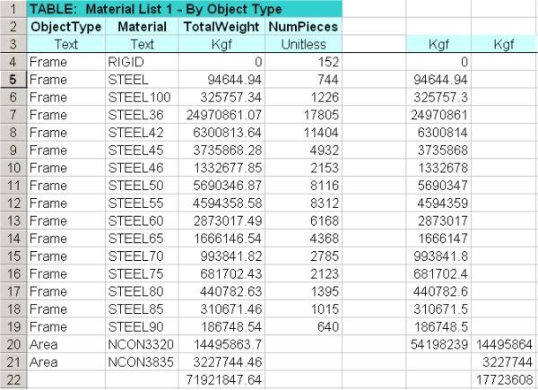
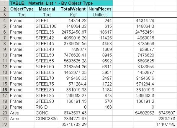
I have reworked my mass and potential energy calculation for WTC1. I haven't formally written it up yet
but I include here images of my spread sheet and a description page. Thanks to Mackey, 3body, Newton,
Dr. Greening and others for providing useful criticism of my previous calculation and also some good sources.

The new mass is 285,000 metric tonnes, which if correct pokes a big hole in Bazant's latest paper. This is
roughly only 10% more than my previous calculation but the method is much better grounded in the NIST
data especially regarding SDLs.

Any constructive feedback is very welcome.

massAndEnergyPart1.jpg


massAndEnergyPart2.jpg


massAndEnergyDesc.jpg
 
Last edited:
Any constructive feedback is very welcome.


NCSTAR 1-6d p176 gives the load on the columns at the aircraft impact region.

WTC2 column loads at 81-82 (loading due to stories 82-110; 29 stories plus roof):

peri: 12367 + 12292 + 17728 + 17673 = 60060 kips
core: 71824 kips
total: 131884 kips = 59.9E6 kg

I added up the mass in your table for the top 29 stories plus the roof and it comes up to 62.9E6 kg, which is close to the NIST value.

If there was more tower mass than what we are accounting for with our estimates, it's probably in the sub-levels or the above-grade stories closer to the ground level.

BZ were using a value of 87E6 kg for the upper block of WTC2. Comparing that with the NIST value shows that they were too high by about 45%:

87/59.9 = 1.45

Compared with your value for the upper block of WTC2, BZ were too high by about 38%.

87/62.9 = 1.38

Greening was using a constant mass per story of 510E6/110 = 4.64E6 kg. The upper block of WTC2 in that case would be 134E6 kg. That's larger than the NIST value by 2.24 or 124%.

134/59.9 = 2.24
 
Greening needed a value of E1 of 0.8 GJ for the model to predict the same collapse rate as what was observed in the first four seconds of WTC2 in his constant mass per story algebraic model. His value of E1 would need to be scaled down roughly by a factor of two if the upper block mass was the NIST value. That would make E1 about 0.4 GJ.

The ratio of E1 to the total falling mass within the footprint is what determines the rate of collapse in a non-shedding model, in addition to the slowing effect of momentum transfer during crush-down. Mass shedding also has a slowing effect.
 
Gregory/Shagster:

I am very happy to see the mass, (which is of course equivalent to the PE), of the Twin Towers being reconsidered. This is a very worthwhile topic of investigation.....

By the way Gregory, just so you know, I used a figure ~ 500,000 tonnes because that was the most "popular" number I saw at the time I was writing my first paper.

I tried very hard to get confirmation of this number and finally gave up.

I have a book full of notes and calculations on this and I suspect that 500,000 tonnes really is an over-estimate although the one caveat I would put on this statement is the question of how much concrete was used in the basement and on the lower core columns as "reinforcement".
 
Last edited:
The mass of the upper 29 stories of WTC2 can be extrapolated to 116 stories and then corrected for extra mass due to the columns becoming thicker near the ground level.

The value of the upper 29 stories plus the roof of WTC2 in NCSTAR 1-6d is 59.9E6 kg. Extrapolating this to 116 stories gives:

59.9*116/29 = 240E6 kg

In another post, I calculated the mass of the perimeter panels at story 96 as 0.088E6 kg. If the core column mass is considered to be similar, then the total core and perimeter column mass including spandels at story 96 is 0.176E6 kg. Extrapolating that to 116 stories gives

0.176*116 = 20.4E6 kg

NIST and the SAP2000 model show that the total column steel in a tower was about 54.2E6 kg. That means that the columns becoming thicker near the base increased the column mass by about

54.2 - 20.4 = 33.8E6 kg

Adding difference that to the extrapolated tower mass gives

240 + 33.8 = 274E6 kg

That's close to Urich's value of 285E6 kg. It's about 21% less than the tower mass value of about 346E6 kg that I was getting for WTC2 from the SAP2000 model when adding up the self-weights and all the other loads that were tacked on to the columns as joint loads. It's possible that there is more than one gravity load scenario in the SAP2000 joint load table, which could mean that loads could be accidentally added up redundantly and give too high a total tower mass. I made sure to not accidentally add up the wind loads as gravity loads.

I need to run an analysis on the SAP2000 model and see what the actual loads were on the columns on a story-by-story basis with no wind loading. That is even better than looking at loads in the SAP2000 tables.

Note that the two mechanical stories in the top 29 stories give a ratio of about 7%, which is the same percentage of the total number of mechanical floors for the entire tower (8/116=0.07). So the upper 29 stories are fairly representative of the whole tower in that respect, not including the extra mass of the hat truss.
 
Last edited:
Greening needed a value of E1 of 0.8 GJ for the model to predict the same collapse rate as what was observed in the first four seconds of WTC2 in his constant mass per story algebraic model. His value of E1 would need to be scaled down roughly by a factor of two if the upper block mass was the NIST value. That would make E1 about 0.4 GJ.

The ratio of E1 to the total falling mass within the footprint is what determines the rate of collapse in a non-shedding model, in addition to the slowing effect of momentum transfer during crush-down. Mass shedding also has a slowing effect.

Absolutely true, it is the ratio that matters. You might have seen that picture that I created by extracting 1xN bitmaps from the dropping antenna, it is really not trivial to fit a curve.

4xmbl3m.png


Anyone ? For wtc1 I got about 0.7g. The problem with the collapse model is also that it is relatively easy to find the speeds as function of the floor, but the collapse time as function of the floor is not easy because you have to assume how the energy per story is lost, you can use an equal force leading to a effective constant acceleration g-E/M_collapsing*h, between the collisions, if you assume the force is working on a small time-period, in the limit of a peak force then you immediately have to lower the velocity using sqrt(v^2-2E/M_c) and use this new velocity and the one at the end of the h distance and take the average. They are not the same, for a rough total collapse time it really doesn't matter but to fit the drop in the beginning you have to be a nitpicker...

HeyLeroy if you are reading, I'm not laughing about 3000 deads, the collapse still gives me the shivers each day.
 
Greg,

I applaud you in making a tabulation that is both easy to read and understand where you're getting your numbers from. One of the things I've noticed in alot of papers from the truther side (such as most from the journal of 9/11 studies) is a lack of clarity in the calculations. I also think that doing it in english and metric is totally awesome.

If you want to sharpen your pencil a little, I can recommend one more addition to the weights you currently have:

Perimeter wall loads. This will include the aluminum siding of the perimeter columns, fire protection on said columns, windows, insulation on the interior and perhaps most importantly: the spandrels. I would guess that this would be around 10-30psf. For a comparison, an EIFS (basically fake/light stucco) system, commonly used in my neck of the woods, is around 15psf. This will likely not be a huge addition, but it won't be insignificant.
 
Tooting my own horn:

In my last letter directed at Gordon Ross, I calculated (based on his assumptions) a total cross-sectional area of steel of 10,402in^2. Based on your numbers, I get 8850in^2. 117% less. Not a huge deal, but I also think the way you distributed the steel puts too much at the top (making less weight on the upper block).

nitpick

10402/8850=1.175
10402 is 17.5% greater than 8850

10402- 0.15(10402)=8850
8850 is 15% less than 10402 not 117%
 
Last edited:
Greg,

I applaud you in making a tabulation that is both easy to read and understand where you're getting your numbers from. One of the things I've noticed in alot of papers from the truther side (such as most from the journal of 9/11 studies) is a lack of clarity in the calculations. I also think that doing it in english and metric is totally awesome.

If you want to sharpen your pencil a little, I can recommend one more addition to the weights you currently have:

Perimeter wall loads. This will include the aluminum siding of the perimeter columns, fire protection on said columns, windows, insulation on the interior and perhaps most importantly: the spandrels. I would guess that this would be around 10-30psf. For a comparison, an EIFS (basically fake/light stucco) system, commonly used in my neck of the woods, is around 15psf. This will likely not be a huge addition, but it won't be insignificant.

Thanks for taking the time to check it out!

The exterior panels were shipped from Pacific Car and Foundry completely assembled including the spandrels. I am assuming the weight is included in the 100,000 tons of steel. I should probably mention this in the description.

Regarding the perimeter wall loads, is the psf the wall area or floor area? I did think about the windows but I didn't want to just make up some numbers. I don't think the NIST documents I have been working from give any info on this. I'll have to check the NCSTAR1-4 and 1-5 series. I suspect there are nuggets of info spread throughout.

Note: If anyone is wondering about the hat truss, the hat truss weight is included in the steel component of the CDL fore the core as an extra 20 psf. This amounts to around 470 tons.
 
Tooting my own horn:

In my last letter directed at Gordon Ross, I calculated (based on his assumptions) a total cross-sectional area of steel of 10,402in^2. Based on your numbers, I get 8850in^2. 117% less. Not a huge deal, but I also think the way you distributed the steel puts too much at the top (making less weight on the upper block).

The last sentence doesn't make sense to me. Do you mean too little steel at the top?
 
Very good job. I know for sure there was some thought that went into this. And I respect the fact that this may be one of the most detailed and accurate calculations of the WTC mass. The process of tweaking this model should be very interesting as well. The only thing I can think of to offer right now is that you may be a little light upstairs :) I mean of course, that your distribution of plate thickness may be off favouring a lighter upper section. From what I have seen and read the thickness of the plate in the core never went below 1/4inch. I think this reduces your ratio from 16:1 to 14:1. I'm not sure if you have a way to adjust this in your model or not? If it is you may want to give it a try and see how it changes the distribution. That's all I got, Nice job.
 
Very good job. I know for sure there was some thought that went into this. And I respect the fact that this may be one of the most detailed and accurate calculations of the WTC mass. The process of tweaking this model should be very interesting as well. The only thing I can think of to offer right now is that you may be a little light upstairs :) I mean of course, that your distribution of plate thickness may be off favouring a lighter upper section. From what I have seen and read the thickness of the plate in the core never went below 1/4inch. I think this reduces your ratio from 16:1 to 14:1. I'm not sure if you have a way to adjust this in your model or not? If it is you may want to give it a try and see how it changes the distribution. That's all I got, Nice job.

Thanks 3Body. One of the guys over at the Scholars for 9/11 Truth and Justice forum has dumped the plate thicknesses from the SAP model. I can't get his link to work though. When I get access to it I may be able to double check. Any possibility you can dump this Shagster?

As you are surely aware it is the net cross sectional area of the steel that matters. The external columns (above 9th floor) all had the same outside dimensions which means the cross sectional area varied almost exactly the same as the plate thickness. That's why I used it, besides the fact that it was known. Since the core has equivalent demands I believe we will see that the 16:1 ratio bears out. Actually, we may find that the ratio is in fact higher. According to my current calculation, the gravity load at sublevel 6 is more than 140 times that of floor 110.

Then there is the little logarithmic thingy in the uppermost part which I'll most likely ignore because the linear approximation puts more steel higher in the building anyway.

Now that I think about it again, the cross sectional area of the steel should vary almost exactly with the loads. If this is true, I could calculate it from the loads and I could ignore the logarithm. Does anyone know if this is valid or not?
 
You want the wall thickness of the core and perimeter columns for each story? I will try to dump this from SAP. I sometimes have trouble creating the data tables in SAP2000. A number of errors sometimes come up. I will try to run SAP on a better computer.
 
Thanks for taking the time to check it out!

The exterior panels were shipped from Pacific Car and Foundry completely assembled including the spandrels. I am assuming the weight is included in the 100,000 tons of steel. I should probably mention this in the description.

Regarding the perimeter wall loads, is the psf the wall area or floor area? I did think about the windows but I didn't want to just make up some numbers. I don't think the NIST documents I have been working from give any info on this. I'll have to check the NCSTAR1-4 and 1-5 series. I suspect there are nuggets of info spread throughout.

Note: If anyone is wondering about the hat truss, the hat truss weight is included in the steel component of the CDL fore the core as an extra 20 psf. This amounts to around 470 tons.

Can you explain how you got to the 100,000 tons (i.e. page number)?

The perimeter wall loads are exterior surface area, not a floor load.
 
Can you explain how you got to the 100,000 tons (i.e. page number)?

The perimeter wall loads are exterior surface area, not a floor load.

Actually I used the popular number not from NIST. I had seen a calculation on the net confirming this. Anyway I went back and found the steel contracts in NIST NCSTAR1-3 p.16. These don't have data for trusses outside the core or grillages.


ext col spandrels 55 800
rolled core and beams 25 900
bifurc col 6 800
ext box col 13 600
core box below 9 13 000
core box above 9 31 000
slab supports below grade 12 000
total 158 100
per tower 79 050

floors trusses from design docs
psf steel outside core 13.5
floors 101
area 30 897
weight 42 128 060
weight tons 21 064

my estimate for the grillages is 459 tons


So the total is 100,573 tons.
 
You want the wall thickness of the core and perimeter columns for each story? I will try to dump this from SAP. I sometimes have trouble creating the data tables in SAP2000. A number of errors sometimes come up. I will try to run SAP on a better computer.

I got access to the dumps but I can't make heads or tails of it.
 
you can use an equal force leading to a effective constant acceleration g-E/M_collapsing*h, between the collisions, if you assume the force is working on a small time-period, in the limit of a peak force then you immediately have to lower the velocity using sqrt(v^2-2E/M_c) and use this new velocity and the one at the end of the h distance and take the average. They are not the same, for a rough total collapse time it really doesn't matter but to fit the drop in the beginning you have to be a nitpicker.

I've tried it both ways in a Greening-type discrete algebraic collapse model and the difference isn't very much. If you haven't already, you can go through the exercise and see if you get the same results as I do.

For v equal to about 8 m/s just after the first impact, the time to drop through a story height after the first impact is 0.415 s if the slow-down is instantaneous just after impact and 0.394 s if the slow-down is spread out evenly through the drop through a story height. That's a difference of 0.022 s or about 5% of the drop time through that particular story.

After 7 impacts, v is about 16 m/s. For 16 m/s, the drop through a story height takes 0.227 s for instantaneous slow-down and about 0.224 s if the slow-down is spread throughout the drop through a story height. That's a difference of 0.003 s or about 1.3%.

The 14th impact occurs at about 4 seconds into the collapse. Just after the 14th impact, v is about 21 m/s and the time difference is about 1.1%.

The above is for a Greening type model for WTC1 with E1=0.8 GJ, E1 being the same for every story, a total tower mass of 510E6 kg, equal mass per story, no shedding, and Greening's measurement of upper block position vs. time.

When E1/m is the value that predicts the observed tower collapse rate during the first four seconds of collapse, the time difference is small. The time difference increases as E1/m increases but I haven't looked at it in detail.
 
Last edited:
A mass issue leftover from another thread.

NCSTAR1-2a p72 and p73 mention concrete encasement of core beams on selected stories and the hat truss region. This apparently is the area load in the SAP2000 model self-weight table that has the labels NCON and CONC. It is extra dead load that wasn't accounted for automatically by the self-weight feature of SAP2000 which added up all the steel weights of the columns, spandrels, core members, and hat truss. It was added in as an area load in the SAP2000 model but still appears in the self-weight dump.

NCSTAR1-2ap72concretebeam.jpg


NCSTAR1-2ap73beamconcrete.jpg
 
Last edited:
The area load which is apparently due to the concrete encasement of beams for particular stories is 17.7E6 kg for WTC1 and and 11.1E6 kg for WTC2. The total steel weight not including the steel in the floor slabs is 54.2E6 kg for WTC1 and 54.6E6 kg for WTC2.

WTC1excelselfobjectkgms.jpg


WTC2excelselfobjectsumkgsm.jpg
 

Back
Top Bottom