Sorry guys, I don't normally read this forum but it seems a great one. Forgive me if I post this answer to one of the replies and then not answer any follow ups as I am not normally monitoring this forum. I have two others that take up most of my available time, but feel free to email me directly with any questions about engineering or products.
By way of introduction, I am Paul McGowan, CEO of PS Audio and the co-inventor of the Noise Harvester along with our Director of Research, Laszlo Juhasz. While I understand the Harvester has a lot of folks in a tizzy, it reall does work to remove noise. At the end of my reply, I describe the basic circuit and how it works. This is not magic, just engineering.
Anyway, here goes:
Let's look at what poster MortFurd has to say:
"Complete, utter, and absolute BS.
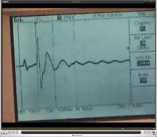
Take a look at the pictures here. Whatever they were measuring, it wasn't a powerline. You get 60 Cycle AC out of an American power outlet. They've got a nasty spike on DC, and there's no AC to be seen. The accompanying text describes the pictures as showing the harvester removing the noise caused by a dimmer. This is a flat out lie. House hold light dimmers work on AC, so the either the description is false or the pictures are wrong. "
OK, let's start with that. If the scope showed the 60Hz waveform, then you couldn't see the very high frequency noise caused by a dimmer. The scope photo shows the dimmer noise only, in fact, it is triggering on the noise and cannot show the 60Hz - one is at a very high frequency and low amplitude and the other is very low frequency and high amplitude.
If it were to show the 60Hz, which is 120 volts, then the high frequency noise would appear like a little zit riding on the 60Hz. And, since the noise amplitude is about 1.2 volts, that zit would be a mere 1% of the 60Hz and thus you wouldn't really see it.
Scopes have the ability to look at a small event in the absence of the larger event that it may be a part of. What you are looking at here is the magnified smaller event without the larger event being visible. I hope that makes sense - as I tried to explain above, you cannot see both - if for no other reason than one event is 99 times larger than the other.
I really object to MortFurd proclaiming this as a "flat out lie". It's amazing to me the arrogance coupled with ignorance that causes someone to proclaim this type of rude mis-statement. MortFurd's conclusion is based soley on his own ignorance and had he asked, instead of jumped to a conclusion, this wouldn't happen.
<EM>
As for the "DC" comment, the scope is set to trigger on the noise caused by the dimmer - so it doesn't move in the way one would expect to see with AC, - so it starts out as a flat line which looks like DC to the untrained eye - so MortFurd assumes it's DC. It's the way the scope handles triggered AC. We do this so we can look at one event and see the change.
Yes dimmers work on AC. They use a device called a triac. The triac chops the AC waveform by remaining off, starting at the zero crossing, then turn on sometime after zero crossing depending on how much light you want. The reason dimmers are so noisy is what I just described. When the triac turns on and starts delivering current, there is a sharp rise in the voltage/current which causes harmonics to be generated (both on the line and in the air). These harmonics are typically in the 8kHz to 12kHz region, where the Harvester is most sensitive. The scope is triggering on this repeating waveform and so it appears not to move.
Why don't you take some of the money you are raking in and actually attend some engineering courses? Specifically, one dealing with the usage of oscilloscopes. You really need help, there.
1. The scope is set to DC coupling on the channel you are measuring. You actually have a DC level of 20Volts with a spike on it.
2. The time base is set to 100microseconds per centimeter. Were there any 60Hz AC in the signal being measured, there would be a significant curve to the shown signal. The width of the screen is 10 centimeters, which is 1000 microseconds, commonly known as 1 millisecond. One cycle of 60Hz AC is 16.7 milliseconds. One half wave is therefore ~8.3 milliseconds. 1/8 of a semicircle would be quite noticeable on the scope picture. The peak of a half wave AC (in the US) would be ~77Volts - 1/8 of that would be about 2 cm on the scope. Even granting worst case (you hit the sine wave exactly at peak in the center of your scope picture) there would still be a downturn of the scope trace of ~1.5Volts at the right and left edges of the picture. That's 3 mm on the scope screen, enough to be seen easily. That's a hash mark and a half, since scopes usually have 2mm hash marks (which your does.)
3. Triggering on DC does not mean (as you imply) that AC is ignored. The scopes are not built to filter anything, with two exceptions a) Frequencies above the scope's design limits are lost and b) DC can be filtered out when measuring AC.
On some of your later comments:
1. If you are using 10X probes, your situation becomes really BAD. The power calculations I wnet through go up by that same factor of 10, and you will be trying to dump more power through a poor little LED - and from the photos that other have posted in this thread, you aren't even using an LED designed for high current. All I see is what looks like a 5mm LED. If you are using a 10X probe, that spike becomes 120Volts. Ouch for your LED.
2. Further clarification: A 10X probe DIVIDES the input signal by 10, so that you must multiply the shown voltage by 10 to get the correct value. Are you telling me you used a 1X probe on a scope set for 10X?
3. Untrained? I spent 10 years working with scopes daily. I've built audio frequency signal analysers. I think I bloody well understand how to read what is shown on the scope face.
4. Powering the LED on noise over 8kHz is no sweat. It won't do you much good, but you can make it blink. So what? I can make an LED blink using nothing but the miniscule amount of power that a crystal radio can receive. Blinking an LED proves bloody zip about power dissipation.
5. Again, if you were dissipating any amount of power capable of making a difference to a properly built amplifier (see Schneibter's info on noise rejection and power supply design) an LED capable of handling that amount of power would blink like a bleeding strobe light.
6. Your description of the operation of the gadget makes quite clear just what is going on. You are powering a blinky on the noise on the powerline. Do you know just how little energy it takes to make a blinky run? Properly designed, a blinky can run on a single AA cell for a year. Your "harverster" isn't neccessarily "harvesting" any significant amount of power at all.
7. Were your device actually effective, it would be more so if you just attached a high power (5watt or more) low resistance resistor to the output of your tranformer. The resistor could dissipate far more power than that poor little LED.
8. Since your scope pictures do NOT show AC, they are at best staged. I consider them to be out and out lies, however, as the staging could only be done to conceal the ineffectiveness of your device. Staging it would allow you to control the impedance of all the signals involved - including the impedance of the spike - which would let you show a higher reduction in the voltage of the spike. What's the current flow during the spike?
How much power does your "harverster" dissipate? Simple question, and you should have the answer to hand - if you have the slightest clue what you are doing.
Please remember that not everyone on this planet is ignorant of basic facts of electricty and the use of test equipment.