5.0: Flight
5.0: FLIGHT
And now, finally, we reach the main issue. I would apologize for the delay, but I feel that it is important to have an understanding of the background issues concerning aerodynamics before tackling flight. Walk before running, and all that stuff. However, you've stuck it through (or skipped straight here, which is fine too) and hopefully have a very basic understanding of fluid dynamics and aerodynamics.
In this section, I am going to discuss the physics behind aircraft flight and maneuvering. I will provide the equations required to determine how aircraft move through the sky, and they're maneuvering capabilities. These equations will allow one to determine what is and is not possible in aircraft dynamics. An invaluable tool, for people who want to test flight paths for feasibility.
I will introduce the equations of motion, and also the limiting factors in aircraft performance. I will show how the limits for turning, climbing, diving and level flight can be determined. I will also discuss ground effect, because I've seen some confusion on that subject in the past.
So sit back, and put on your reading glasses. This is the meat of my post(s), and the main issue I'm addressing today. I hope you will be able to understand it, and apply it well.
5.1: Equations of Motion
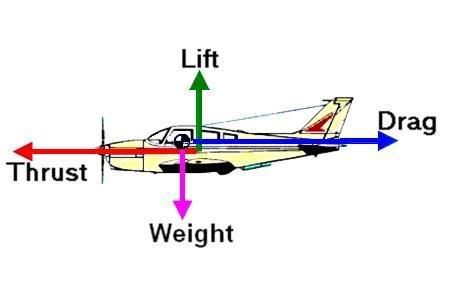
All of you have probably seen the diagrams of airplanes showing the four major forces of flight: lift, drag, thrust and weight. You're going to see it again, as Figure 7 (below).
Figure 7: The Four Forces of Flight
So you see the four forces. To make the equations I will be presenting easier to read, I will be labeling the thrust force as T and the weight force (or force due to gravity) as W. Lift and drag will continue to be designated as L and D, respectively, as has been done throughout this discussion already. These are the forces that every aircraft has to deal with. By balancing and unbalancing them, the aircraft can control it's motion.
Motion is derived from forces. A net force will result in an acceleration. Balanced forces (no net force) will result in no acceleration. It is vitally important that you understand that acceleration, like velocity, is a vector (it has both direction and magnitude) and as such, can be either positive (speed increases) or negative (speed decreases). If there is no acceleration (no net force), it does not mean that the object is not moving. It merely means that the object will continue to move at whatever velocity it already has, be that zero or non-zero. I point this out because some individuals on this forum have serious difficulty understanding that.
The equations of motion are derived from Newton's Second Law, which is written as:
[latex]\sum F = \sum m a[/latex]
Where
F = some force
m = mass of the aircraft
a = acceleration of the aircraft
Every formula for maneuvering I will present can be derived from the above equation. I will not give details of substitutions, so if you are having trouble understanding how I arrived at a certain equation, feel free to ask.
5.2: Lift to Drag Ratio
It will be useful to define a ratio between the lift and the drag. This ration is of the form L/D, or lift force divided by drag force. This ratio will pop up a few ties in the following sections, so it is well that you are aware of what it is.
If you go back to the equations for the lift and drag coefficients, you may notice that the terms are identical, except for L, D, C
L and C
D. This is interesting. It means that the ratio between the lift and drag forces is the exact same as the ratio between the lift and drag coefficients, C
L/C
D. The two can be used interchangeably. A useful development.
There are many charts plotting the change of L/D with respect to velocity (each aircraft will have its own such chart, with a unique L/D curve). These plots are invaluable when analyzing the performance capabilities of an aircraft.
5.3: Level Flight
When analyzing aircraft motion, it is necessary to do a summation of the forces acting on the aircraft. The easiest way to do this is by treating the horizontal and vertical forces (and components) separately. To this end, I will write a force balance for an aircraft with F
H representing the horizontal forces and F
V representing the vertical forces. Assume positive is to the left (horizontal axis) and upward (vertical axis) in Figure 7.
[latex]\sum F_{H} = T - D = m a_{horizontal}[/latex]
[latex]\sum F_{V} = L - W = m a_{vertical}[/latex]
For horizontal flight, all that is necessary is that the lift balances the weight.
[latex]L = W = q_{\infty} S C_{L}[/latex]
For unaccelerated flight, the thrust balances the drag.
[latex]T = D = q_{\infty} S C_{D}[/latex]
We can divide these two equations and discover that the thrust required for steady, level flight can be calculated very easily once you know the L/D ratio (which is dependent on velocity).
[latex]T_{R} = \frac{W}{C_{L} / C_{D}}[/latex]
From the thrust required, you can determine how much power is required for a given velocity.
[latex]P_{R} = T_{R} V_{\infty}[/latex]
What this means is that if you know the power an aircraft has available, you can determine it's maximum velocity by finding out when the required power matches the available power. Not that this changes depending on altitude, angle of attack, and environmental conditions.
5.4: Stalling
I've mentioned stalling before. To recap: A stall is when the wing loses lift. This happens when the flow over the wing separates from the wing surface. This can occur due to either low speeds or high angles of attack.
The stalling speed of an aircraft is the minimum speed it can fly at before stall occurs. This can be calculated from he lift coefficient.
[latex]V_{\infty} = \sqrt{\frac{2W}{\rho_{\infty} S C_{L}}}[/latex]
Note that this depends on the lift coefficient, which is in turn dependent on angle of attack. This means that for any angle of attack, you can find the minimum speed required to remain airborne. If the speed required is faster than the aircraft can fly at a given angle of attack, then stall will occur. This creates a limit to the rate at which an aircraft can climb.
5.5: Climbing
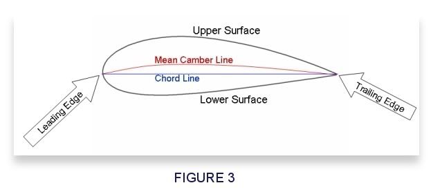
You will recall that I defined the angle of attack (α) as the angle between the free-stream flow direction (sometimes called flight path) and the chord line. I will now introduce the climb angle, c, which is the angle between the horizontal and the direction of flight (or the free stream flow direction). You can see this labeled in Figure 8 (below).
Figure 8: Forces on a Climbing Aircraft
Summing up the equations of motion in the vertical direction, we get:
[latex]V_{\infty} \sin c = \frac{TV_{\infty} - DV_{\infty}}{W} [/latex]
Here I need to introduce a few new terms:
“rate of climb” is the vertical component of an aircraft's velocity, and is defined as
[latex]R/C = V_{\infty} \sin c[/latex]
“excess power” is defined as
[latex]excess power = T V_{\infty} - D V_{\infty}[/latex]
And so for any given velocity, climb angle, and excess power (dependent on the aircraft's powerplant) we can find an estimation for the rate of climb. I would be amiss if I neglected to mention that this is an approximation, and only valid for small angles of climb (less than about 20 degrees). At greater angles of climb, the drag coefficient actually gets smaller than for level flight, and the accuracy of the above equation will be greatly reduced. But it is a useful estimation.
Related to the climb rate is the “time to climb”.
As before, I'm not going to derive this equation. If you want to do it, it is easily done. The time to climb is found using the following integral:
[latex]t = \int^{h_{2}}_{h_{1}} \frac{dh}{R/C}[/latex].
Keep in mind that R/C will change with altitude.
5.6: Turning, Pulling Up, Pulling Down
Until this point, we have been looking at aircraft in steady flight. That is, the flight path has been constant. We haven't looked at changing flight paths yet. This can occur either by turning or pulling up or down. These maneuvers are all very similar, and I will handle them all together.
Figure 9: Turning Flight
Turning flight is quite easy to analyze. We only need to define a few variables, none of which are complicated. We need to define a radius of turn, R, the turn rate, ω, and the load factor, n.
The load factor is the ratio of lift to weight. This is what people refer to when they talk about “g's” in a turn. It is the force accelerating the aircraft around the curve. For example, an aircraft pulling 2 g's would be lifting twice it's weight, hence L/W would be equal to 2.
The radius of a turn is determined from Newton's Second Law and a little geometry. As usual, I'm not going to derive this equation. It would just bore people. So I'll simply give the final result.
[latex]R = \frac{V^2_{\infty}}{g \sqrt{n^2 - 1}}[/latex]
<--- ETA: I don't know why these won't format right.
Where g is the acceleration due to gravity, and the rest of the terms you know.
Next, we can calculate the rate of turn, or angular velocity.
[latex]\omega = \frac{V_{\infty}}{R} = \frac{g \sqrt{n^2 - 1}}{V_{\infty}}[/latex]
From these equations, you can determine the g force required for a turn if you know the velocity of the aircraft and radius of the turn. It is then easy to determine whether the maneuver you have described is possible for the aircraft being considered (more on this shortly).
The analysis are similar for pull up and pull-down maneuvers. The only difference is that the curve flow is vertical rather than horizontal.
Pull-up:
[latex]R = \frac{V^2_{\infty}}{g(n - 1)}[/latex]
<--- ETA: I don't know why these won't format right.
[latex]\omega = \frac{g(n - 1)}{V_{\infty}}[/latex]
Pull-down:
[latex]R = \frac{V^2_{\infty}}{g(n + 1)}[/latex]
<--- ETA: I don't know why these won't format right.
[latex]\omega = \frac{g(n + 1)}{V_{\infty}}[/latex]
Painless, yes? It is now a trivial exercise to determine the maximum turning rate and minimum turning radius for any given aircraft. All you need is the wing loading (W/S, as opposed to load factor which is L/W). We discussed wing loading in Section 4. I told you it would come in handy.
[latex]R_{min} = \frac{2}{\rho_{\infty} g C_{L, max}} \frac{W}{S}[/latex]
[latex]\omega_{max} = g \sqrt{\frac{\rho_{\infty} C_{L, max} n_{max}}{2(W/S)}}[/latex]
C
L, max is the maximum lift coefficient. You will have to look at a table to determine at what speed this occurs. n
max is the maximum load factor. It is actually a function of C
L, max.
[latex]n_{max} = \frac{1}{2} \rho_{\infty} V^2_{\infty} \frac{C_{L,max}}{W/S}[/latex]
5.7: Gliding
This is not really a necessary topic, but it is interesting and simple, so I'll cover it.
Gliding flight is a situation in which the aircraft is unpowered. In this situation, the equilibrium glide angle (angle at which the flight forces are balanced) is dependent entirely on the lift to drag ration, L/D.
[latex]glide angle = \arctan{\frac{1}{L/D}}[/latex]
Arctan is the inverse tangent function. It is normally written as tan
-1. I personally prefer arctan, as it prevents me from getting confused between tan
-1(angle) and tan (angle)
-1.
5.8: Ground Effect
One last topic to cover here. As I said earlier, I am covering this due to instanced of misunderstanding of the ground effect in the past.
Earlier we discussed vortices, and how they can reduce lift and increase parasitic drag. I mentioned that the winglets you see on modern airliners reduce the effect of vortices on the wing. But what happens to those vortices when an aircraft is near the ground?
I'll tell you what happens: They get blocked, and the air beneath the wing gets slightly compressed. This removes the loss in lift caused by vortices, and at the same time increases the pressure differential over the wing that provides lift. Because of this, aircraft at low altitudes need less power to fly (no vortex-induced drag) and less lift (due to the lack of vortices and the compression effects). This is why ground-effect (or wing-in-ground effect) vehicles are able to move extremely efficiently at high speeds.
Ground effect does not prevent the aircraft from reaching the ground. That can still happen. It just gives a slight boost in the lift the aircraft generates, so the aircraft will have to reduce the lift (by slowing down or changing pitch) a little more closer to the ground than was required at higher altitudes to maintain it's rate of descent.
5.9: Summary
I have now delivered into your hands the formulas that show the limits of aircraft maneuverability. You should now be able to take a proposed flight path, and determine whether it is physically possible for the aircraft under consideration. I'll give you a hint: if the turning radius or climb rate of the proposed flight path exceeds the turning radius or climb rate the aircraft can deliver at the specified velocities, then the flight path is not physically possible.
 ). This section will deal with lift and drag. There are two other fairly important concepts I could cover here, but as they are not necessary to what I will discuss in Section 5, I will merely mention them with links to more information. They are the
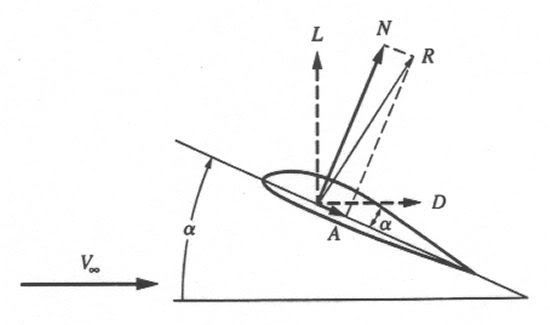


")


 Haven't you seen their big list of people who know at least enough to keep silent as Balsamo mangles the facts in their collective name?